Which of the following waveforms has the lowest percentage voltage ripple?
A Single-phase
B Three-phase, six-pulse
C Three-phase, 12-pulse
D High-frequency
D High-frequency
-Single-phase current has a 100% voltage drop between peak voltages. Three-phase current decreases this voltage drop considerably. Three-phase, six-pulse current has about a 13% voltage drop between peak voltages, and three-phase, 12-pulse current has only about a 4% drop between peak voltages. However, high-frequency current is almost constant potential, having less than 1% voltage ripple.
The chest radiograph shown in the figure below demonstrates
A motion
B focal-spot blur
C double exposure
D grid cutoff
C double exposure
-The radiographic image seen in the figure demonstrates double exposure. Notice the double image of the ribs, humerus, and clavicle, especially on the left side of the chest. The anatomic parts and diaphragm are sharply defined, not blurry, as they would be in the case of motion. Focal-spot blur would also cause a slight blur/loss of resolution of anatomic details. Grid cutoff would appear loss of receptor exposure in part or all of the image.
Advantages of direct digital radiography over computed radiography (CR) include
- direct digital is less expensive.
- direct digital has immediate readout.
- IPs are not needed for direct digital .
A 1 only
B 1 and 2 only
C 2 and 3 only
D 1, 2, and 3
C 2 and 3 only
-Computed radiography (CR) is less expensive primarily because it is compatible with existing equipment. Direct digital radiography requires existing equipment to be modified or new equipment purchased. The image plate (IP) can also be used for mobile studies, though direct digital is currently available for mobile imaging as well. After image processing, the IP is erased and reused. DR offers the advantage of immediate visualization of the x-ray image; in CR there is a short delay.
In which type of equipment does kilovoltage decrease during the actual length of the exposure?
- Condenser-discharge mobile equipment
- Battery-operated mobile equipment
- Fixed x-ray equipment
A 1 only
B 1 and 2 only
C 2 and 3 only
D 1, 2, and 3
A 1 only
-Mobile x-ray machines are compact and cordless and are either the battery-operated type or the condenser-discharge type. Condenser-discharge mobile x-ray units do not use batteries; this type of mobile unit requires that it be charged before each exposure. A condenser (or capacitor) is a device that stores electrical energy. The stored energy is used to operate the x-ray tube only. Because this machine does not carry many batteries, it is much lighter and does not need a motor to drive or brake it. The major disadvantage of the capacitor/condenser-discharge unit is that as the capacitor discharges its electrical charge, the kilovoltage gradually decreases throughout the length of the exposure—therefore limiting tube output and requiring recharging between exposures.
Which of the following is used in digital fluoroscopy, replacing the image intensifier's television camera tube?
A Solid-state diode
B Charge-coupled device
C Photostimulable phosphor
D Vidicon
B Charge-coupled device
-In digital fluoroscopy (DF), the image-intensifier output screen image is coupled via a charge-coupled device (CCD) for viewing on a display monitor. A CCD converts visible light to an electrical charge that is then sent to the analog-to-digital converter (ADC) for processing. When output screen light strikes the CCD cathode, a proportional number of electrons are released by the cathode and stored as digital values by the CCD. The CCD's rapid discharge time virtually eliminates image lag and is particularly useful in high-speed imaging procedures such as cardiac catheterizations. CCD cameras have replaced analog cameras (such as the Vidicon and Plumbicon) in new fluoroscopic equipment. CCDs are more sensitive to the light emitted by the output phosphor (than the analog cameras) and are associated with less “noise.” DF eliminates the need for cassette-loaded spot films and/or 100-mm spot films. DF photo-spot images, which are simply still-frame images, need no chemical processing, require less patient dose, and offer post processing capability. DF also offers “road-mapping” capability. “Road-mapping” is a technique useful in procedures involving guidewire/catheter placement. During the fluoroscopic examination, the most recent fluoroscopic image is stored on the monitor, thereby reducing the need for continuous x-ray exposure. This technique can offer significant reductions in patient and personnel radiation exposure.
When using the smaller field in a dual-field image intensifier,
- the image is magnified
- the image is brighter
- a larger anatomic area is viewed
A 1 only
B 1 and 3 only
C 2 and 3 only
D 1, 2, and 3
A 1 only
-When a dual-field image intensifier is switched to the smaller field, the electrostatic focusing lenses are given a greater charge to focus the electron image more tightly. The focal point, then, moves further from the output phosphor (the diameter of the electron image is, therefore, smaller as it reaches the output phosphor), and the brightness gain is somewhat diminished. Hence, the patient area viewed is somewhat smaller and is magnified. However, the minification gain has been reduced, and the image is somewhat less bright.
The number 2 in Figure 5–2 indicates the
A nickel focusing cup
B actual focal spot
C effective focal spot
D anode stem
A nickel focusing cup
-The figure illustrates the component parts of a rotating-anode x-ray tube enclosed within a glass envelope (number 3) to preserve the vacuum necessary for x-ray production. Number 4 is the rotating anode with its beveled focal track at the periphery (number 8) and its stem (at number 5). Numbers 6 and 7 are the stator and rotor, respectively—the two components of an induction motor—whose function it is to rotate the anode. Number 1 is the filament of the cathode assembly, which is made of thoriated tungsten and functions to liberate electrons (thermionic emission) when heated to white hot (incandescence). Number 2 is the molybdenum focusing cup, which functions to direct the liberated filament electrons to the focal spot.
What information must be included on an x-ray image for it to be considered as legitimate legal evidence?
- Name of facility where exam performed
- Examination date
- Date of birth
A 1 only
B 1 and 2 only
C 2 and 3 only
D 1, 2, and 3
B 1 and 2 only
-X-ray images are often subpoenaed as court evidence in cases of medical litigation. In order to be considered as legitimate legal evidence, each x-ray image must contain certain essential and specific patient information. Essential information that must be included on each image is patient identification, the identity of the facility where the x-ray study was performed, the date that the study was performed, and a right- or left-side marker.
Other useful information that may be included, but that is not considered essential, is additional patient demographics such as their date of birth, the identity of the referring physician, the time of day that the study was performed, and the identity/initials of the radiographer performing the examination.
Which of the following circuit devices operate(s) on the principle of self-induction?
- Autotransformer
- Choke coil
- High-voltage transformer
A 1 only
B 1 and 2 only
C 2 and 3 only
D 1, 2, and 3
B 1 and 2 only
-The principle of self-induction is an example of the second law of electromagnetics (Lenz's law), which states that an induced current within a conductive coil will oppose the direction of the current that induced it. It is important to note that self-induction is a characteristic of AC only. The fact that AC is constantly changing direction accounts for the opposing current set up in the coil. Two x-ray circuit devices operate on the principle of self-induction. The autotransformer operates on the principle of self-induction and enables the radiographer to vary the kilovoltage. The choke coil also operates on the principle of self-induction; it is a type of variable resistor that may be used to regulate filament current. The high-voltage transformer operates on the principle of mutual induction.
In order to erase a CR PSP storage plate, it must be exposed to high-intensity:
A Heat
B X-radiation
C Microwaves
D Light
D Light
-High intensity visible light (D) produces the wavelength energy necessary to release residual stored energy from these imaging plates. Some residual energy remains stored in the IP after it has been scanned in a CR reader. In order to prevent artifacts on successive radiographic images, it is important to rid the IP of all stored energy. To do this, a high intensity light that is brighter than the stimulating laser light is exposed to the release of any residual stored energy (signal) in the IP. Heat (A) is used in thermal printers used to print hard copy digital images. X-radiation (B) would deposit energy within the image plate, rendering it useless for subsequent diagnostic radiographic exposures. Microwaves (C) are not used as an energy source to erase CR image plates.
If obtaining multiple images on one image plate, it is important to:
A Allow for X-ray tube cooling between successive exposures
B Avoid shielding of the image plate at all times to avoid field recognition errors
C Properly shield each exposed and unexposed area during the imaging of each individual image
D Expose the AP or PA projection in the right lower portion of the image plate
C Properly shield each exposed and unexposed area during the imaging of each individual image
-Successive static exposures taken on one or more image plates rarely would cause overheating of the X-ray tube (A). Shielding of the image plate for multiple exposures is important to avoid intrafield scatter radiation exposure and a possible field recognition error (B). The keys to multiple fields on one IP are symmetry and uniform distribution. One should only use 3-on-1 distribution for fingers and toes where the amount of intrafield scatter is low. If larger body structures are done 3-on-1, the intrafield scatter will reduce the contrast unless the unexposed areas are shielded between exposures (C). The specific location of any projection on an image plate does not discount the importance of including one projection on one image plate (D).
A device used to ensure reproducible radiographs, regardless of tissue-density variations, is the
A AEC
B penetrometer
C moving grid
D compensating filter
A AEC
-Radiographic reproducibility is an important concept in producing high-quality diagnostic images. Radiographic results should be consistent and predictable not only in terms of positioning accuracy but also with respect to technical factors. AEC devices (ionization chambers) automatically terminate the x-ray exposure once a predetermined quantity of x-rays has penetrated the part, thus ensuring consistent results.
To compensate for variations in gain across a digital receptor, which of the following maintenance steps should be taken?
A Conduct a calibration correction for image nonuniformity
B Increase or decrease the exposure factors to compensate
C Install a variable resistor to adjust the electrical supply to the unit
D Keep a log for at least 30 days to confirm consistent variations before making any adjustments
A Conduct a calibration correction for image nonuniformity
-Digital systems require that a uniformity correction (A) be applied to compensate for variations in gain across the receptor. This calibration for nonuniformity (also called shading correction) must be repeated on a periodic basis; the frequency depends on the digital device and ranges from daily to semi-annually. The exposure factors should not be adjusted (B) as a result of gain variations. This would be an unacceptable practice, especially if the exposure is increased, as this will cause unnecessary patient radiation dosage. Technologists should never alter the electrical supply (C) to the digital unit. Gain adjustments can be made to the equipment by simply adjusting the gain setting. Keeping a log for 30 days (D) to track the variations in gain would not facilitate timely correction to ensure that optimal diagnostic images are being produced.
Capacitor-discharge mobile x-ray units use capacitors to power the
- x-ray tube
- machine locomotion
- braking mechanism
A 1 only
B 2 only
C 1 and 2 only
D 1, 2, and 3
A 1 only
-Mobile x-ray machines are smaller and more compact than their fixed counterparts in the radiology department. It is important that they be relatively easy to move, that their size allows entry into patient rooms, and that their locks enable securing of the x-ray tube into the required positions. Mobile x-ray machines are cordless and are either the battery-operated type or the condenser-discharge type.Condenser-discharge mobile x-ray units do not use batteries; this type of mobile unit requires that it be charged before each exposure. A condenser (or capacitor) is a device that stores electrical energy. The stored energy is used to operate the x-ray tube only. Because this machine does not carry many batteries, it is much lighter and does not need a motor to drive or brake it. The major disadvantage of the capacitor/condenser-discharge unit is that as the capacitor discharges its electrical charge, the kilovoltage gradually decreases throughout the length of the exposure—hence, the need for recharging between exposures.
A device used to measure the luminance response and uniformity of monitors used in digital imaging is called a
A Penetrometer
B Densitometer
C Sensitometer
D Photometer
D Photometer
-Two types of photometers (D) are commonly used to measure the luminance response and uniformity of monitors used in digital imaging: near-range and telescopic. Near-range photometers are used for measuring the monitor’s luminance at close range, whereas telescopic photometers measure this from a distance of one meter. Background ambient light should be kept constant when either photometer is used. A penetrometer (or aluminum step wedge) (A) is a device used for quality control testing in film radiography. After making an exposure of this device while it rests on top of a film cassette, the film within the cassette is chemically processed. The resultant image demonstrates multiple steps of densities. The densities can be measured by a densitometer (B) to determine the film contrast index and other processing-related factors. A sensitometer (C), which is an electrical device, can be used in lieu of the penetrometer and projects a preset (visible light) exposure on the film in the darkroom. After the film is processed, multiple steps of densities, similar to those achieved using the penetrometer, are demonstrated and can then be measured by a densitometer in the same fashion (A, B, C).
An advantage of coupling the image intensifier to the TV camera or CCD via a fiber-optic coupling device is its
- compact size
- durability
- ability to accommodate auxilary imaging devices
A 1 only
B 1 and 2 only
C 1 and 3 only
D 1, 2, and 3
B 1 and 2 only
-The image intensifier can be coupled to the TV camera via a fiber-optic bundle or via a lens coupling device. The fiber-optic connection offers less fragility, more compactness, and ease of maneuverability. The objective lens can use the, now infrequently used, auxiliary imaging devices such as a cine camera or spot-film camera.
Characteristics of low ratio focused grids include the following:
1.they have a greater focal range
2.they are less efficient in collecting SR
3.they can be used inverted
A 1 only
B 1 and 2 only
C 2 and 3 only
D 1, 2, and 3
B 1 and 2 only
-Grid ratio compares the height of the lead strip to the distance between the lead strips. Focused grids have their lead strips angled so as to parallel the divergent x-ray beam. The higher the grid ratio, the greater the grid's efficiency in absorbing scattered radiation before it reaches the image receptor—but the more critical the centering and distance specifications. Although higher ratio focused grids absorb more SR they have a narrower focal range (focusing distance) and grid/tube centering becomes much more critical. Focused grids must not be accidentally inverted—to do so would cause the lead strips to be placed exactly in the path of the lead strips (grid cutoff), everywhere but in the center of the grid.
The long axis of the laser beam moving transversely back and forth across the image plate in a CR reader is called the:
A Scan/translation mode
B Zig-zag scan mode
C Slow scan direction
D Fast scan direction
D Fast scan direction
-Slow scan direction (C) speed refers to the linear travel speed of the image plate through the CR reader. The IP moves slowly through the transport system of a CR reader and this movement is considered theslow-scan direction. The laser light in the reader is rapidly reflected by an oscillating polygonal mirror that redirects the beam through a special lens called the f-theta lens, which focuses the light on a cylindrical mirror that reflects the light toward the IP. This light moves back and forth very rapidly to scan the plate transversely, in a raster pattern, and this movement of the laser beam across the IP is therefore called the fast-scan direction (D). Scan/translation mode (A) and Zig-zag mode (B) are not terms used to describe the laser beam movement back and forth across the image plate while it travels through the CR reader (A).
When radiographing a cross-table lateral hip or axial shoulder using CR, one method of creating a collimation margin at the bottom of the radiograph is to:
A Use a narrow lead strip at the bottom edge of the IP, but out of the anatomy
B Only one collimation margin is necessary, so this would not be necessary
C Make two exposures with suspended respiration; one for the uppermost anatomy, then a second for the dependent anatomy
D Expose the anatomy as is and use the post-processing cropping feature
A Use a narrow lead strip at the bottom edge of the IP, but out of the anatomy
-The difference between cross-table hips or axial shoulders is that most often only one collimated edge is visible (because soft tissue extends to edge of table/IP). If a second collimated border is not detected, the exposure field is not accurately located, processing/rescaling errors will likely occur. One may create a second collimation margin by using a narrow (approx. 1 in.) lead strip at the bottom of the IP to generate a “margin” between the exposure field and the edge of the cassette (A). If only one collimation margin is included on the receptor (B), the radiographer has improperly centered the anatomical part. This may result in misidentification of the exposure field and therefore, cause a processing error. Two exposures at different central ray locations (C) would result in two images where a misaligned image of the anatomy for both exposures would result. The cropping feature (D) is a post-processing function that will not affect the system’s ability to recognize the exposure field.
Double-focus x-ray tubes have two
- focal spots.
- filaments.
- anodes.
A 1 only
B 1 and 2 only
C 1 and 3 only
D 2 and 3 only
B 1 and 2 only
-A double-focus tube has two focal-spot sizes available. These focal spots actually are two available paths on the focal track. There are also two filaments. When the small focal spot is selected, the small filament is heated, and electrons are driven across to the smaller portion of the focal track. When the large focal spot is selected, the large filament is heated, and electrons are driven across to the larger portion of the focal track.
In the CR reader, some of the laser light is redirected to a reference detector by way of a(n):
A Beam splitter
B Analog-to-digital converter
C Photomultiplier tube
D f-theta lens
A Beam splitter
-The laser beam in a CR reader is directed to a reference detector by way of a beam splitter (A). Optical components called beam splitters are used to divide input light into two separate parts. Beam splitters are found in many laser or illumination systems, and light can be split according to overall intensity or by wavelength. A reference detector enables the CR reader to monitor the laser beam intensity and make adjustments for any fluctuations that may occur, thereby ensuring constant laser beam intensity and uniform release of stored phosphor energy. The PMT, or photomultiplier tube (C), receives the light emitted from a CR phosphor plate as it is scanned by the laser beam, which, in turn, sends an electronic signal to the ADC. The ADC, or analog-to-digital convertor (B), receives an electrical signal from a photomultiplier tube that receives the light emitted from a CR image plate as it is scanned by the laser beam. The ADC changes this electrical (analog) signal to a binary (digital) signal to be used by the processing computer. The f-theta lens in a CR reader focuses the laser light onto a cylindrical mirror, which, in turn, reflects this light toward the image plate as it traverses the scanning section of the CR reader (D).
All the following are components of the image intensifier except
A the photocathode
B the focusing lenses
C the TV monitor
D the accelerating anode
C the TV monitor
-The input phosphor of an image intensifier receives remnant radiation emerging from the patient and converts it to a fluorescent light image. Directly adjacent to the input phosphor is the photocathode, which is made of a photoemissive alloy (usually a cesium and antimony compound). The fluorescent light image strikes the photocathode and is converted to an electron image. The electrons are focused carefully, to maintain image resolution, by the electrostatic focusing lenses, through the accelerating anode and to the output phosphor for conversion back to light. The TV monitor is not part of the image intensifier but serves to display the image that is transmitted to it from the output phosphor.
For the same FOV, spatial resolution will be improved using
A a smaller matrix
B a larger matrix
C fewer pixels
D shorter SID
B a larger matrix
-Field of view (FOV) refers to the area being viewed. The FOV can be increased or decreased. As the FOV is increased, the part being examined is magnified; as the FOV is decreased, the part returns closer to actual size. Pixel size is affected by changes in either the FOV or matrix size. For example, if the matrix size is increased, for example, from 256 × 256 to 512 × 512, pixel size must decrease. If FOV increases, pixel size must increase. Pixel size is inversely related to resolution. As pixel size decreases, resolution increases. Decreasing SID would decrease spatial resolution.
A QA program serves to
- keep patient dose to a minimum
- keep radiographic quality consistent
- ensure equipment efficiency
A 1 only
B 1 and 2 only
C 1 and 3 only
D 1, 2, and 3
D 1, 2, and 3
-A QA program includes regular overseeing of all components of the imaging system—equipment calibration, film and cassettes, processor, x-ray equipment, and so on. With regular maintenance, testing, and repairs, equipment should operate efficiently and consistently. In turn, radiographic quality will be consistent, and repeat exposures will be minimized, thereby reducing patient exposure.
While indirect digital detectors use a scintillator (phosphor) to convert X-ray energy, direct detectors use a:
A Photoconductor
B Scintillator
C Charged coupled device
D Histogram detector screen
A Photoconductor
-Indirect digital systems use scintillators/phosphors (B) to convert X-ray energy, whereas direct digital systems use a photoconductor (A) to covert this energy. This energy is subsequently converted by either a charged coupled device (CCD) array or photodiode array (coupled with a thin film transistor array) in the two types of indirect systems, or by a TFT array in a direct system. Finally, both indirect and direct digital system conversions result in an analog signal that is converted to a digital signal by the analog-to-digital convertor (ADC). A scintillator (phosphor) receives X-ray energy and converts it to light in an indirect digital detector system. In direct conversion digital detectors, an X-ray photoconductor (B) is used to convert this energy. Some indirect digital detectors use charged coupled devices (CCD), but a scintillator (phosphor) converts the X-ray energy and, through light optics, transfers this energy to the CCD (C). The histogram (D) is a computerized graphic display of the X-ray intensities received by the detectors in direct or indirect digital detector systems (or by the image plate in CR systems). There is no histogram detector screen (D).
Although the stated focal-spot size is measured directly under the actual focal spot, focal-spot size actually varies along the length of the x-ray beam. At which portion of the x-ray beam is the effective focal spot the largest?
A At its outer edge
B Along the path of the central ray
C At the cathode end
D At the anode end
C At the cathode end
-X-ray tube targets are constructed according to the line-focus principle—the focal spot is angled (usually 12–17 degrees) to the vertical (Figure 4–34). As the actual focal spot is projected downward, it is foreshortened; thus, the effective focal spot is always smaller than the actual focal spot. As it is projected toward the cathode end of the x-ray beam, the effective focal spot becomes larger and approaches the actual size. As it is projected toward the anode end, it gets smaller because of the anode heel effect.
Radiography using a collimated thin fan X-ray beam would be found in:
A Scanned projection radiography (SPR) of the chest
B Long bone measurement radiography
C Radiography of foreign objects
D Fluoroscopic evaluation of the ureters, as they are thin structures
A Scanned projection radiography (SPR) of the chest
-In scanned projection radiography (SPR) of the chest (A), the X-ray beam is collimated to a thin fan by pre-patient collimators. Post-patient image-forming X-rays likewise are collimated to a thin fan that corresponds to a detector array consisting of a scintillation phosphor, usually NaI or CsI, which is married to a linear array of CCDs through a fiberoptic path. Long bone measurement radiography (B) uses a special ruler (called a Bell-Thompson ruler) that is placed beneath and between the patient’s legs. It contains centimeter markers that are displayed on specific collimated portions of the anatomy on a large radiographic film. Typical collimated exposures, taken one at a time, are focused on the hip joints, knee joints, and ankle joints. By taking any two centimeter markings corresponding to any two anatomical areas, the smaller number can be subtracted from the larger number to determine the length between the two anatomical areas. Any bilateral discrepancies would indicate either uneven growth or otherwise disproportionate lengths of the lower extremities. Radiography of foreign objects (C) requires either a static full-field exposure or collimated exposure on a radiographic cassette containing a radiographic film. This radiographic investigation to discover foreign objects requires a single exposure per projection. The resultant processed radiographs (minimum of two at 90 degree projections) will demonstrate the location of a foreign object, particularly if the atomic number of the foreign object differs from the surrounding anatomic tissues and organs. Fluoroscopic evaluation of the ureters (D) first, involves fluoroscopy, which involves a constant X-ray exposure to demonstrate real-time imaging of the anatomical structures. The ureters are typically examined during an intravenous urogram (IVU) after an iodinated contrast medium is injected in to the patient’s venous system, usually via the antecubital vein route. Once the contrast medium is excreted by the kidneys, the ureters will begin to fill and, upon a static X-ray exposure on a 14” x 17” film, will be demonstrated as fine, white (because of the high atomic number of iodine), and linear structures running longitudinally to the urinary bladder.
A fill factor of 80% in direct or indirect digital radiography means that:
A 20% of the pixel area is occupied by the detector electronics with 80% representing the sensing area
B 80% of the pixel area is occupied by the detector electronics with 20% representing the sensing area
C The saturation level will be unacceptable
D Only 20% of the image will be captured
A 20% of the pixel area is occupied by the detector electronics with 80% representing the sensing area
-The fill factor is expressed as a percentage. In this case (A), 80% means that 20% of the pixel area is occupied by the detector electronics with 80% representing the sensing area which, in turn, represents the image. Larger fill factors indicate large sensing areas; larger fill factors (and sensing areas) indicate better spatial and contrast resolution. In (B), 20% means that 80% of the pixel area is occupied by the detector electronics with 20% representing the sensing area which, in turn, represents the image. Saturation (C) means that beyond a certain exposure level, a large number of the pixels will be at the maximum digital value (black) so that there is no signal difference in the very high exposure areas, resulting in a loss of anatomical structures in that region. This is an undesirable effect. Collimation defines the exposure field, so 20% of the image would only occur if 20% of the anatomical area were to be exposed and captured (D).
Anode angle will have an effect on the
- severity of the heel effect
- focal-spot size
- heat-load capacity
A 1 only
B 2 only
C 1 and 2 only
D 1, 2, and 3
D 1, 2, and 3
-As the anode angle is decreased (made steeper), a larger actual focal spot may be used while still maintaining the same small effective focal spot. Because the actual focal spot is larger, it can accommodate a greater heat load. However, with steeper (smaller) anode angles, the anode heel effect is accentuated and can compromise film coverage.
Capacitor-discharge mobile x-ray units
- use a grid-controlled x-ray tube
- are typically charged before the day's work
- provide a direct-current output
A 1 only
B 2 only
C 1 and 3 only
D 1, 2, and 3
C 1 and 3 only
-There are two main types of mobile x-ray units—capacitor-discharge and battery-powered. The capacitor-discharge units consist of a capacitor, or condenser, which is given a charge and then stores energy until the x-ray tube uses it to produce x-rays. The charge may not be stored for extended periods, however, because it tends to “leak” away; the capacitor must be charged just before the exposure is made. Its x-ray tube is grid-controlled, permitting very fast (short) exposure times. Capacitors discharge a direct current (as opposed to single- or three-phase pulsating current) in which the kilovoltage decreases by a value of approximately 1 kV/mAs. Thus, although the value at the onset of the exposure may be 20 mAs and 80 kVp, at the end of the exposure, the kilovoltage value will be approximately 60 kVp. In addition, capacitor-discharge units permit only limited milliampere-seconds values, usually 30 to 50 mAs per charge.
The figure below is representative of
A the anode heel effect
B the line-focus principle
C the inverse-square law
D the reciprocity law
C the inverse-square law
-The figure illustrates that as distance from a light/x-ray source increases, the light/x-rays diverge and cover a larger area; the quantity of light/x-ray available per unit area becomes less and less as distance increases. The intensity (quantity) of light/x-ray decreases according to the inverse-square law; that is, the intensity at a particular distance from its source is inversely proportional to the square of the distance. As the distance between the x-ray tube and image receptor increases, exposure rate (and,therefore, receptor exposure) decreases according to the inverse-square law.
Because the anode's focal track is beveled, x-ray photons can freely diverge toward the cathode end of the x-ray tube. However, the “heel” of the focal track prevents x-ray photons from diverging toward the anode end of the tube. This results in varying intensity with fewer photons at the anode end and more photons at the cathode end
X-ray tube targets are constructed according to the line-focus principle—the focal spot is angled to the vertical. As the actual focal spot is projected downward, it is foreshortened; thus, the effective focal spot is always smaller than the actual focal spot.
Which of the following will serve to increase the effective energy of the x-ray beam?
- Increase in added filtration
- Increase in kilovoltage
- Increase in milliamperage
A 1 only
B 2 only
C 1 and 2 only
D 1, 2, and 3
C 1 and 2 only
-As filtration is added to the x-ray beam, the lower-energy photons are removed, and the overall energy or wavelength of the beam is greater. As kilovoltage is increased, more high-energy photons are produced, and again, the overall, or average, energy of the beam is greater. An increase in milliamperage serves to increase the number of photons produced at the target but is unrelated to their energy.
Objectionable widening of the histogram in CR can be caused by all of the following, except:
A Off-focus and scatter radiation outside of the exposure field
B Windowing
C Improper pre-exposure anatomical selection
D Subtraction
D Subtraction
-Off-focus and scatter radiation outside of the exposure field would be detected as additional information and, therefore, would widen the histogram (A), resulting in a processing error. Histogram analysis errors can result in rescaling errors and exposure indicator determination errors. Windowing (B) is a post-processing method of adjusting the brightness and contrast in the digital image. There are two types of windowing: level and width. Window level adjusts the overall image brightness. When the window level is increased, the image becomes darker. When decreased, the image becomes brighter. Window width adjusts the ratio of white to black, thereby changing image contrast. Narrow window width provides higher contrast (short-scale contrast), whereas wide window width will produce an image with less contrast (long-scale contrast). Improper pre-exposure anatomical selection (C) (e.g., selecting chest versus the intended foot selection) can interfere with proper histogram assignment (and display) for the anatomical part of interest. In digital image subtraction (D), the pixel values from post-contrast images are electronically subtracted from pixel values from the first pre-contrast (mask) image to show contrast-filled blood vessels with the other structures (e.g., bone) removed in order to enhance the diagnostic impressions of the radiologist, and is unrelated to histogram changes.
Due to the high sensitivity of digital detectors to low intensity radiation (background, scatter and/or off-focus radiation), there is likely to be scatter and off-focus radiation contributing to the image outside the collimation margins. Since many radiologists find this distracting, the most appropriate radiographer action would be to:
A Use film-screen imaging only
B Apply a black border to the image before it is printed or sent to PACS
C Expose the anatomical parts as is; there is nothing that can be done to improve the presentation of the image(s) due to the inherent sensitivity of the system
D Reduce exposure factors by one-half to ensure minimal scatter and off-focus radiation
B Apply a black border to the image before it is printed or sent to PACS
-Film-screen radiography has been abandoned in most hospitals and imaging centers. Most of these institutions no longer maintain a darkroom or resources to produce film-screen images (A). Many radiologists find scatter and off-focus radiation distracting when viewing images. The appropriate response to scatter and off-focus exposure outside the collimation margin is to apply a black border to the image before it is printed or sent to PACS (B). Close collimation should be used to minimize scatter radiation (C). The exposure factors must be appropriate for the anatomical part being imaged. Halving the appropriate mAs or kVp (D) will result in image mottle or inadequate penetration of the part, respectively.
All of the following are advantages of digital fluoroscopic imaging systems over conventional fluoroscopic imaging systems, except:
A Post-processing capability to enhance image contrast
B Increased image acquisition speed
C No need for pulsed or continuous radiation exposure
D Higher milliamperage settings can be used
C No need for pulsed or continuous radiation exposure
-All fluoroscopic imaging (conventional and digital) requires either pulsed or continuous X-ray exposure (C) to provide a dynamic image of the anatomical area of interest. In digital fluoroscopic units, the X-ray tube actually operates in the radiographic mode. However, multiple exposures are made in succession to produce the dynamic image. In these systems, the X-ray generator must be capable of switching on (also called interrogation time) and off (also called extinction time) rapidly in less than 1 ms. The digitized image in a digital fluoroscopy system can be post-processed to enhance image contrast (A), similar to the post-processing that can be done with computed and direct capture static radiographic images. One of the advantages of a digital fluoroscopic system over a conventional fluoroscopic system is the elimination of the television camera tube from the imaging chain, thereby increasing image acquisition speed (B). Either a charge-coupled device or a flat panel image receptor is used to generate electrical signals that can be digitized in a much faster and efficient way, when compared to conventional fluoroscopy. During digital fluoroscopy, the X-ray tube actually operates in the radiographic mode using higher milliamperage settings (D). Tube current is measured in hundreds of milliamperes (mA) rather than less than 5 mA, as in image intensified fluoroscopy. This is not a problem, as the exposures are made in rapid succession and in a pulsed manner (also called pulsed progression fluoroscopy).
Fluorescent light is collected from the image intensifier output phosphor and converted to an electronic video signal by the
1.TV camera tube.
2.CCD.
3.coaxial cable.
A 1 only
B 1 and 2 only
C 2 and 3 only
D 1, 2, and 3
B 1 and 2 only
-There are two devices that can take the fluorescent image from the image intensifier output phosphor and convert it to an electronic video signal: a TV camera tube and a CCD. A TV camera tube is found on older fluoroscopic equipment. Today's newer fluoroscopic equipment uses a CCD (charge-coupled device) to accomplish this task. The CCD is a solid-state device that offers much better spatial resolution and less image noise.
A coaxial cable follows the TV camera or CCD in the fluoroscopic chain. It is used to connect the TV camera or CCD to the TV monitor.
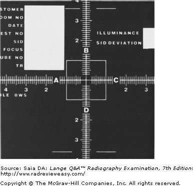
A test radiograph like the one pictured in Figure A would be made by the radiation safety officer (RSO) or equipment service person and is used to evaluate
A focal spot size.
B linearity.
C collimator alignment.
D spatial resolution.
C collimator alignment.
-The radiograph illustrates testing done to evaluate the x-ray beam and light beam alignment. Light-localized collimators must be tested periodically and must be accurate to within 2% of the SID. Linearity means that a given mA, using different mA stations with appropriate exposure time adjustments, will provide consistent intensity. A star pattern would be used to evaluate focal spot resolution, and a parallel line-type resolution pattern could also be used to evaluate spatial resolution.
One advantage of digital imaging in fluoroscopy is the ability to perform "road-mapping." Road-mapping
1. keeps the most recent fluoroscopic image on the screen.
2. aids in the placement of guidewires and catheters.
3. reduces the need for continuous x-ray exposure to the patient.
A 1 only
B 1 and 2 only
C 2 and 3 only
D 1, 2, and 3
D 1, 2, and 3
-There are several advantages of electronic/digital fluoroscopy. Electronic/digital fluoroscopic images are produced with less patient exposure and can be post processed (windowed to improve/enhance the image). The fluoroscopic still-frame images can be stored and/or transmitted to a TV monitor. Another advantage is the ability to perform "road-mapping." In this procedure, the most recent fluoroscopic image is retained on the screen/monitor (last image hold) is retained on the screen/monitor. Road-mapping is particularly useful in procedures that require guidewire/catheter placement. The frame-hold function eliminates the need for continuous fluoroscopy, thereby reducing patient exposure.
The x-ray beam and collimator light field must coincide to within
A 10% of the OID
B 2% of the OID
C 10% of the SID
D 2% of the SID
D 2% of the SID
-There are many radiation protection devices and laws associated with today's x-ray equipment. For example, the collimator light must accurately indicate the size and location of the x-ray beam to within 2% of the SID. Equipment that does not function properly contributes to excessive patient exposure, in the form of repeat examinations, and to poor image quality.
The image intensifier's input phosphor generally is composed of
A cesium iodide
B zinc cadmium sulfide
C gadolinium oxysulfide
D calcium tungstate
A cesium iodide
-The image intensifier's input phosphor receives the remnant beam from the patient and converts it to a fluorescent light image. To maintain resolution, the input phosphor is made of cesium iodide crystals. Cesium iodide is much more efficient in this conversion process than was the phosphor used previously, zinc cadmium sulfide. Calcium tungstate was used in intensifying screens in film screen imaging for many years prior to the development of rare earth phosphors such as gadolinium oxysulfide.
Periodic equipment care includes evaluation of the
1.kV.
2.milliamperage.
3.timer.
A 1 only
B 1 and 3 only
C 2 and 3 only
D 1, 2, and 3
D 1, 2, and 3
-Radiographic results should be consistent and predictable, not only with regard to positioning accuracy, but with respect to exposure factors and image clarity as well. X-ray equipment and accessories must be calibrated periodically as part of an ongoing QA program. Image receptors should be cleaned and evaluated regularly. The quantity (mAs) and quality (kVp) of the primary beam have a big impact on the quality of the image, and their accuracy, along with that of the x-ray timer, should be assessed regularly. Kilovoltage accuracy can be evaluated with a Wisconsin test tool or digital meter and must be accurate to within 5 kV (+/` 10%). The focal spot should be tested periodically to evaluate its impact on image sharpness.
Star and wye configurations are related to
A autotransformers
B three-phase transformers
C rectification systems
D AECs
B three-phase transformers
-The terms star and wye (or delta) refer to the configuration of transformer windings in three-phase equipment. Instead of having a single primary coil and a single secondary coil, the high-voltage transformer has three primary and three secondary windings—one winding for each phase (Figure 5–13). Autotransformers operate on the principle of self-induction and have only one winding. Three-phase x-ray equipment often has three autotransformers.
To be used more efficiently by the x-ray tube, alternating current is changed to unidirectional current by the
A filament transformer.
B autotransformer.
C high-voltage transformer.
D rectifiers.
D rectifiers.
-Rectifiers (solid-state or the older valve tubes) permit the flow of current in only one direction. They serve to change AC, which is needed in the low-voltage side of the x-ray circuit, to unidirectional current. Unidirectional current is necessary for the efficient operation of the x-ray tube. The rectification system is located between the secondary coil of the high-voltage transformer and the x-ray tube. The filament transformer functions to adjust the voltage and current going to heat the x-ray tube filament. The autotransformer varies the amount of voltage being sent to the primary coil of the high-voltage transformer so that the appropriate kVp can be obtained. The high-voltage transformer "steps up" the voltage to the required kilovoltage and steps down the amperage to milliamperage.
Fractional-focus tubes, with a 0.3-mm focal spot or smaller, have special application in
A magnification radiography
B fluoroscopy
C tomography
D image intensification
A magnification radiography
-Magnification radiography may be used to demonstrate small, delicate structures that are difficult to image with conventional radiography. Because OID is an integral part of magnification radiography, the problem of magnification unsharpness arises. The use of a fractional focal spot (0.3 mm or smaller) is essential to the maintenance of image sharpness in magnification films. Radiographic rating charts should be consulted because the heat load to the anode may be critical in magnification radiography. The long exposures typical of image-intensified fluoroscopy and tomography make the use of a fractional focal spot generally impractical and hazardous to the anode.
X-ray tube life may be extended by
- using high milliampere-second, low- kilovoltage exposure factors.
- avoiding lengthy anode rotation.
- avoiding exposures to a cold anode.
A 1 only
B 1 and 2 only
C 2 and 3 only
D 1, 2, and 3
C 2 and 3 only
-X-ray tube life may be extended by using exposure factors that produce a minimum of heat (a lower milliampere-seconds and higher kilovoltage combination) whenever possible. When the rotor is activated, the filament current is increased to produce the required electron source (thermionic emission). Prolonged rotor time, then, can lead to shortened filament life owing to early vaporization. Large exposures to a cold anode will heat the anode surface, and the temperature difference between surface and interior can cause cracking of the anode. This can be avoided by proper warming of the anode prior to use, thereby allowing sufficient dispersion of heat through the anode.
Referring to the simplified x-ray circuit shown in Figure 6–5, what is indicated by the number 3?
A Step-up transformer
B Autotransformer
C Filament circuit
D Rectification system
A Step-up transformer
-The autotransformer is labeled 1, the primary coil of the high-voltage transformer is labeled 2, the grounded milliampere meter is labeled 4, and the filament circuit is labeled 6. The rectification system, which is used to change alternating current to unidirectional current, is indicated by number 5. The rectification system is located between the secondary coil of the high-voltage (step-up) transformer (number 3) and the x-ray tube (number 7).
Tungsten alloy is the usual choice of target material for radiographic equipment because it
- has a high atomic number
- has a high melting point
- can readily dissipate heat
A 1 only
B 1 and 2 only
C 2 and 3 only
D 1, 2, and 3
D 1, 2, and 3
-The x-ray anode may be a molybdenum disk coated with a tungsten–rhenium alloy. Tungsten, with a high atomic number (74), produces high-energy x-rays quite efficiently. Since a great deal of heat is produced at the target, its high melting point (3410°C) helps to avoid damage to the target surface. Heat produced at the target should be dissipated readily, and tungsten's conductivity is similar to that of copper. Therefore, as heat is applied to the focus, it can be conducted throughout the disk to equalize the temperature and thus avoid pitting, or localized melting, of the focal track.
All the following are associated with the anode except
A the line-focus principle
B the heel effect
C the focal track
D thermionic emission
D thermionic emission
-The rotating anode has a target (or focal spot) on its beveled edge that forms the target angle. As the anode rotates, it constantly turns a new face to the incoming electrons; this is the focal track. The portion of the focal track that is bombarded by electrons is the actual focal spot, and because of the target's angle, the effective or projected focal spot is always smaller (line-focus principle). The anode heel effect refers to decreased beam intensity at the anode end of the x-ray beam. The electrons impinging on the target have “boiled off” the cathode filament as a result of thermionic emission.
Which of the following is (are) characteristics of the x-ray tube?
- The target material should have a high atomic number and a high melting point.
- The useful beam emerges from the port window.
- The cathode assembly receives both low and high voltages.
A 1 only
B 2 only
C 1 and 2 only
D 1, 2, and 3
D 1, 2, and 3
-Anode target material with a high atomic number produces higher-energy x-rays more efficiently. Because a great deal of heat is produced at the target, the material should have a high melting point so as to avoid damage to the target surface. Most of the x-rays generated at the focal spot are directed downward and pass through the x-ray tube's port window. The cathode filament receives low-voltage current to heat it to the point of thermionic emission. Then, high voltage is applied to drive the electrons across to the focal track.
Using a multifield image intensifier tube, which of the following input phosphor diameters will provide the best spatial resolution?
A 35 cm
B 25 cm
C 17 cm
D 12 cm
D 12 cm
-Multifield image intensifier tubes are usually either dual-field or tri-field and are designed this way in order to permit magnification imaging. As voltage is applied to the electrostatic focusing lenses, the focal point moves back—closer to the input phosphor—and a smaller portion of the input phosphor is utilized. As a result, the FOV decreases and magnification increases, producing better spatial resolution. At the same time, brightness is decreased requiring an increase in mA (therefore increased patient dose). This increase in mA increases image quality. It can be likened to an increase in signal-to-noise ratio (SNR), with mA being the signal.
Which of the following modes of a trifield image intensifier will result in the highest patient dose?
A Its 25-cm. mode
B Its 17-cm. mode
C Its 12-cm. mode
D Diameter does not affect patient dose
C Its 12-cm. mode
-Most image-intensifier tubes are either dual-field or trifield, indicating the diameter of the input phosphor. When a change to a smaller-diameter mode is made, the voltage on the electrostatic focusing lenses is increased, and the result is a magnified but dimmer image. The milliamperage will be increased automatically to compensate for the loss in brightness with a magnified image, resulting in higher patient dose in the smaller-diameter modes.
The process of “leveling and windowing” of digital images determines the image
A spatial resolution
B contrast
C pixel size
D matrix size
B contrast
-The digital images' scale of contrast, or contrast resolution, can be changed electronically through leveling and windowing of the image. It is often stated simply that window level controls density and window width controls contrast. However, the level control specifically determines the central ormiddensity of the scale of contrast, whereas the window control determines the total number of grays (to the right and left of the central/middensity). Matrix and pixel sizes are related to (spatial) resolution of digital images.
If a high-voltage transformer has 100 primary turns and 35,000 secondary turns, and is supplied by 220 V and 75 A, what are the secondary voltage and current?
A 200 A and 77 V
B 200 mA and 77 kVp
C 20 A and 77 V
D 20 mA and 77 kVp

B 200 mA and 77 kVp
-The high-voltage, or step-up, transformer functions to increase voltage to the necessary kilovoltage. It decreases the amperage to milliamperage. The amount of increase or decrease is dependent on the transformer ratio-the ratio of the number of turns in the primary coil to the number of turns in the secondary coil. The transformer law is as follows:
All of the following are steps that should be used to accomplish quality control (QC) in digital radiography, except:
A Acceptance testing
B Establishment of baseline performance
C Monitoring patient size to evaluate variations in equipment performance
D Diagnosis of changes in performance
C Monitoring patient size to evaluate variations in equipment performance
-Patient size variations are expected in a radiology department. Equipment operation is expected to respond accordingly to variations in the size of the patient, although image quality may vary, as expected (C). Acceptance testing (A) is the initial opportunity to determine whether the imaging equipment meets the requirements of state and regulatory agencies, as well as special requirements that may be included in the purchasing contract. It is important to determine acceptable performance before the imaging device is used for patients. It is also important to conduct the acceptance testing with the vendor service engineer present, so that deficiencies may be corrected immediately.Establishment of baseline performance (B) is an important QC step. New equipment is expected to perform well, but it is important to monitor indicators of change and establish control limits with subsequent use. Control limits determine the maximum deviation from normal that is considered allowable before initiating corrective action. Diagnosing changes in equipment performance (D) is an important component of a QC program. When a decrease in performance expectations is observed and corrective action is taken, it is important to verify that performance has returned to normal levels. This may require more comprehensive tests than the usual performance indicators and possibly a repeat of the complete acceptance testing procedures.
A photostimulable phosphor plate is used with
A CR
B Direct DR
C fluoroscopic intensifying screens
D image-intensified fluoroscopy
A CR
-A photostimulable (light-stimulated) phosphor plate, or simply image plate (IP), is used in CR. The CR image plate (IP) contains a photostimulable phosphor that is the image receptor. On exposure, the PSP stores information. The IP is placed into a special scanner/processor where the PSP is scanned with a laser light and the stored image is displayed on the computer monitor.
Of what material is the x-ray tube component numbered 5 in Figure 7–18 made?
A Cesium
B Nickel
C Molybdenum
D Tungsten
D Tungsten
-The figure illustrates the x-ray tube component parts. Number 1 indicates the thoriated tungsten filament, which functions to release electrons when heated. Number 2 is the nickel focusing cup, which directs these electrons toward the anode's focal track. Number 4 is the rotating anode, and number 5 is the anode's focal track. The focal track is made of a tungsten-rhenium alloy (for extra protection from heat). When high-speed electrons are suddenly decelerated at the target, their kinetic energy is changed to x-ray photon energy.
All the following x-ray circuit devices are located between the incoming power supply and the primary coil of the high-voltage transformer except
A the circuit breaker.
B the kilovoltage selector.
C the rectifiers.
D the autotransformer.
C the rectifiers.
-All circuit devices located before the primary coil of the high-voltage transformer are said to be on the primary, or low-voltage, side of the x-ray circuit. The timer, circuit breaker, autotransformer, kilovoltage selector switch, and (prereading) kilovoltage meter are all located in the low-voltage circuit. The rectifiers, however, are placed after the secondary coil of the high-voltage transformer and before the x-ray tube.
Which of the following information is necessary to determine the maximum safe kilovoltage using the appropriate x-ray tube rating chart?
- Milliamperage and exposure time
- Focal-spot size
- Imaging-system speed
A 1 only
B 1 and 2 only
C 2 and 3 only
D 1, 2, and 3
B 1 and 2 only
-Given the milliamperage and exposure time, a radiographic rating chart enables the radiographer to determine the maximum safe kilovoltage for a particular exposure. Because the heat load an anode will safely accept varies with the size of the focal spot and the type of rectification, these variables must be identified. Each x-ray tube has its own radiographic rating chart. The speed of the imaging system has no impact on the use of a radiographic rating chart.
Conditions that contribute to x-ray tube damage include
- lengthy anode rotation
- exposures to a cold anode
- low-milliampere-seconds/high- kilovoltage exposure factors
A 1 only
B 1 and 2 only
C 1 and 3 only
D 1, 2, and 3
B 1 and 2 only
-X-ray tube life may be extended by using exposure factors that produce a minimum of heat, that is, a lower milliampere-seconds and higher kilovoltage combination, whenever possible. When the rotor is activated, the filament current is increased to produce the required electron source (thermionic emission). Prolonged rotor time, then, can lead to shortened filament life as a result of early vaporization. Large exposures to a cold anode will heat the anode surface, and the big temperature difference can cause cracking of the anode. This can be avoided by proper warming of the anode prior to use, thereby allowing sufficient dispersion of heat through the anode.
Which of the following combinations will offer the greatest heat-loading capability?
A 17-degree target angle, 1.2-mm actual focal spot
B 10-degree target angle, 1.2-mm actual focal spot
C 17-degree target angle, 0.6-mm actual focal spot
D 10-degree target angle, 0.6-mm actual focal spot
B 10-degree target angle, 1.2-mm actual focal spot
-The smaller the focal spot, the more limited the anode is with respect to the quantity of heat it can safely accept. As the target angle decreases, the actual focal spot can be increased while still maintaining a small effective focal spot. Therefore, group (B) offers the greatest heat-loading potential, with a steep target angle and a large actual focal spot. It must be remembered, however, that a steep target angle increases the heel effect, and IR coverage may be compromised.
The line-focus principle refers to the fact that
A the actual focal spot is larger than the effective focal spot
B the effective focal spot is larger than the actual focal spot
C x-rays travel in straight lines
D x-rays cannot be focused
A the actual focal spot is larger than the effective focal spot
-A distinction is made between the actual focal spot and the effective, or projected, focal spot. The actual focal spot is the finite area on the tungsten target that is actually bombarded by electrons from the filament. The effective focal spot is the foreshortened size of the focus as it is projected down toward the image receptor. This is called line focusing or the line-focus principle. The quoted focal-spot size is the effective focal-spot size.
A backup timer for the AEC serves to
- protect the patient from overexposure
- protect the x-ray tube from excessive heat
- adjust image contrast
A 1 only
B 1 and 2 only
C 2 and 3 only
D 1, 2, and 3
B 1 and 2 only
-When an AEC is installed in an x-ray circuit, it is calibrated to deliver the most appropriate receptor as required by the radiologist. Once the part being radiographed has been exposed to produce the correct receptor exposure, the AEC automatically terminates the exposure. The manual timer should be used as a backup timer; in case the AEC fails to terminate the exposure, the backup timer would protect the patient from overexposure and the x-ray tube from excessive heat load. Image contrast in CR/DR is determined by computer software.
All of the following are daily quality control (QC) steps to ensure optimal diagnostic images on a digital display monitor, except:
A Turn on the monitor and allow it to warm up
B Evaluate luminance, reflection, noise and glare
C Make sure that the monitor is dust-free on the viewing surface
D Evaluate the QC patterns at the periphery and verify that all letters and numbers appear
D Evaluate the QC patterns at the periphery and verify that all letters and numbers appear
-In order to ensure optimal diagnostic images on a digital display monitor, the QC pattern should be evaluated at the center and corners to verify that all letters and numbers can be visualized (D). Turning on the monitor and allowing it to warm up (A) prior to evaluating images is an important step in daily quality control efforts. Evaluating the luminance, reflection, noise and glare (B) at the beginning of each day is important to ensure optimal image clarity for the radiologists and other physicians. It is important that the monitor viewing surface is dust-free (C) in order to provide a clear optical evaluation.
Referring to the anode cooling chart in Figure 5–9, if the anode is saturated with 300,000 heat units (HU), how long will the anode need to cool before another 160,000 HU can be safely applied?
A 3 minutes
B 4 minutes
C 5 minutes
D 7 minute
B 4 minutes
-Each x-ray exposure made by the radiographer produces hundreds or thousands of heat units at the target. If the examination requires several consecutive exposures, the potential for extreme heat load is increased. Just as each x-ray tube has its own radiographic rating chart, each tube also has its own anode cooling curve to describe its unique heating and cooling characteristics. An x-ray tube generally cools most rapidly during the first 2 minutes of nonuse. First, note that the tube is saturated with heat at 300,000 HU. In order for another 160,000 HU to be safely applied, the x-ray tube must first release 160,000 HU, which means that it has to cool down at least to 140,000 HU. Find the 140,000 HU point on the vertical axis and follow across to where it intersects with the cooling curve. It intersects at about the 4-minute point.
Major components of a CR reader include all of the following, except:
A Laser source
B Image plate transport mechanism
C Thin-film transistor
D Analog-to-digital convertor
C Thin-film transistor
-The laser source (A) is a major component of a CR reader because it is this light energy that, when distributed on the image plate’s PSP (photostimulable phosphor), releases the stored energy from the X-ray exposure to the PSP, which can then be used to produce the diagnostic anatomical image. The major components of a computed radiography (CR) reader include the laser source, image plate (IP) transport mechanism (B), light channeling guide, photodetector (photomultiplier tube), and the analog-to-digital convertor (ADC). The TFT, i.e. thin-film transistor (C), is a component found in flat-panel detector type digital systems. The analog-to-digital convertor (D) is a device that receives the analog signal from the CR reader and converts this signal into binary code to be used by the computer for read-out and post-processing.
In digital imaging, artifacts arise from a number of sources, including which of the following?
A Imaging hardware
B Image processing software
C Operator error artifacts
D All of these may be sources of image artifacts
D All of these may be sources of image artifacts
-In digital imaging, artifacts arise from a number of sources. Imaging hardware artifacts include aged, cracked phosphor storage plates and mishandled and poorly cared for IPs. Image processing software artifacts can arise from incorrectly selected processing algorithms or from exposure field recognition issues from improper collimation, positioning, or sizing. Operator error artifacts can arise from incorrectly stored IPs, incorrect use of equipment, inaccurate selection of factors, etc.
Geometric blur can be evaluated using all the following devices except
A star pattern
B slit camera
C penetrometer
D pinhole camera
C penetrometer
-Focal-spot size accuracy is related to the degree of geometric blur, that is, edge gradient or penumbra. Manufacturer tolerance for new focal spots is 50%; that is, a 0.3-mm focal spot actually may be 0.45 mm. Additionally, the focal spot can increase in size as the x-ray tube ages—hence the importance of testing newly arrived focal spots and periodic testing to monitor focal-spot changes. Focal-spot size can be measured with a pinhole camera, slit camera, or star-pattern-type resolution device. The pinhole camera is rather difficult to use accurately and requires the use of excessive tube (heat) loading. With a slit camera, two exposures are made; one measures the length of the focal spot, and the other measures the width. The star pattern, or similar resolution device such as the bar pattern, can measure focal-spot size as a function of geometric blur and is readily adaptable in a QA program to monitor focal-spot changes over a period of time. It is recommended that focal-spot size be checked on installation of a new x-ray tube and annually thereafter.
All of the following are components of a television picture tube (cathode ray tube), except:
A Electron gun
B Glass envelope
C Signal plate
D Focusing coil
C Signal plate
-A signal plate (C) is a component of a television camera tube, such as the Vidicon. An electron gun (A) is used in the cathode section of a television picture tube (cathode ray tube (CRT)) to generate electrons that are accelerated onto the output phosphor and converted to visible light. An outer glass envelope (B) is necessary in a CRT to contain a vacuum, thereby eliminating air molecules that would otherwise impede the electrons traveling from the electron gun to the output phosphor. The focusing coil (D) is a component of a CRT. Its function is to keep the electron beam produced by the electron gun confined to a narrow stream.
The ability of an x-ray unit to produce constant radiation output at a given mAs, using various combinations of mA and time is called
A linearity.
B reproducibility.
C densitometry.
D sensitometry.
A linearity.
-Each of the four factors are used as part of a complete quality assurance (QA) program. Linearity means that a given mAs, using different mA stations with appropriate exposure time adjustments, will provide consistent intensity. Reproducibility means that repeated exposures at a given technique must provide consistent intensity. Sensitometry and densitometry are used in evaluation of the film processor, part of a complete QA program.
An exposed image plate will retain its original image quality for about
A 2 hours
B 8 hours
C 24 hours
D 48 hours
B 8 hours
-Computed radiography image plates (IP) have a protective function (for the PSP within) and can be used in the Bucky tray or directly under the anatomic part; they need not be light-tight because the PSP is not light sensitive. The IP has a thin lead-foil backing to absorb backscatter. Inside the IP is the photostimulable phosphor (PSP) storage plate. This PSP within the IP has a layer of europium-activated barium fluorohalide that serves as the IR as it is exposed in the traditional manner and receives the latent image. The PSP can store the latent image for several hours; after about 8 hours, noticeable image fading will occur.
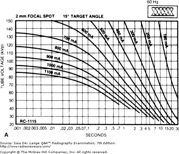
In the radiographic rating charts shown below, what is the maximum safe mA that may be used with 0.1-second exposure and 120 kVp, using the three-phase, 2-mm focal spot x-ray tube
A 400
B 500 C
600
D 700

C 600
-Find the correct chart for the three-phase, 2-mm focal spot x-ray tube. Locate 0.1 second on the horizontal (seconds) axis and follow it up to where it intersects with the 120-kVp line on the vertical (kVp) axis. They intersect midway between the 600- and 700-mA curves, at approximately 650 mA. Thus, 600 mA is the maximum safe milliamperage for this particular group of exposure factors and x-ray tube
The x-ray tube used in CT must be capable of
- high-speed rotation
- short pulsed exposures
- withstanding millions of heat units
A 1 only
B 1 and 2 only
C 2 and 3 only
D 1, 2, and 3
D 1, 2, and 3
-A CT imaging system has three component parts—a gantry, a computer, and an operating console. The gantry component includes an x-ray tube, a detector array, a high-voltage generator, a collimator assembly, and a patient couch with its motorized mechanism. Although the CT x-ray tube is similar to direct-projection x-ray tubes, it has several special requirements. The CT x-ray tube must have a very high short-exposure rating and must be capable of tolerating several million heat units while still having a small focal spot for optimal resolution. To help tolerate the very high production of heat units, the anode must be capable of high-speed rotation. The x-ray tube produces a pulsed x-ray beam (1–5 ms)using up to about 1,000 mA.
Which of the following systems function(s) to compensate for changing patient/part thicknesses during fluoroscopic procedures?
A Automatic brightness control
B Minification gain
C Automatic resolution control
D Flux gain
A Automatic brightness control
-Parts being examined during fluoroscopic procedures change in thickness and density as the patient is required to change positions and as the fluoroscope is moved to examine different regions of the body that have varying thickness and tissue densities. The automatic brightness control functions to vary the required milliampere-seconds and/or kilovoltage as necessary. With this method, patient dose varies, and image quality is maintained. Minification and flux gain contribute to total brightness gain.
Magnification fluoroscopy is only possible with:
A Decreased patient dosage
B Multifield image intensifiers
C Decreased fluoroscopic time
D Increased efficiency of X-ray production
B Multifield image intensifiers
-Magnification fluoroscopy requires that a multifield image intensifier (B) be used to allow reduction of the X-ray field size to the input phosphor area. Smaller input phosphor field sizes produce magnified images of the anatomical areas being evaluated at the output phosphor. Magnification mode in fluoroscopy actually increases patient dosage (A), as more radiation is necessary to produce the brightness levels needed to view the images. The magnification mode should therefore be used only when necessary to enhance diagnostic interpretation of small anatomical areas in question (e.g., the gallbladder or duodenal bulb). Fluoroscopy time should be limited to that which is absolutely necessary in order to ensure proper practice of ALARA. However, the time needed to evaluate the anatomical areas in question is not limited to a certain time. Magnification fluoroscopy neither increases or decreases fluoroscopic evaluation time (C). X-ray production efficiency is a function of the generator and X-ray tube (D) providing the necessary X-ray energy to produce the fluoroscopic image. Magnification fluoroscopy, therefore, does not alter the efficiency of X-ray production.
What x-ray tube component does the number 8 in Figure 5–11 indicate?
A Anode stem
B Rotor
C Stator
D Focal track
A Anode stem
-The figure illustrates the component parts of a rotating-anode x-ray tube enclosed within a glass envelope (number 3) to preserve the vacuum necessary for x-ray production. Number 4 is the rotating anode with its beveled focal track at the periphery (number 8) and its stem (at number 5). Numbers 6 and 7 are the stator and rotor, respectively—the two components of an induction motor—whose function it is to rotate the anode. Number 1 is the filament of the cathode assembly, which is made of thoriated tungsten and functions to liberate electrons (thermionic emission) when heated to white hot (incandescence). Number 2 is the molybdenum focusing cup, which functions to direct the liberated filament electrons to the focal spot.
Resolution in CR increases as
- laser beam size decreases
- monitor matrix size decreases
- PSP crystal size decreases
A 1 only
B 1 and 2 only
C 1 and 3 only
D 1, 2, and 3
C 1 and 3 only
-Spatial resolution in CR is impacted by the size of the PSP, the size of the scanning laser beam, and monitor matrix size. High-resolution monitors (2–4 MP, megapixels) are required for high-quality, high-resolution image display. The larger the matrix size, the better is the image resolution. Typical image matrix size (rows and columns) used in chest radiography is 2,048 × 2,048. As in traditional radiography, spatial resolution is measured in line pairs per millimeter. As matrix size is increased, there are more and smaller pixels in the matrix and, therefore, improved spatial resolution. Other factors contributing to image resolution are the size of the laser beam and the size of the PSP phosphors. Smaller phosphor size improves resolution —anything that causes an increase in light diffusion will result in a decrease in resolution. Smaller phosphors in the PSP plate allow less light diffusion. Additionally, the scanning laser light must be of the correct intensity and size. A narrow laser beam is required for optimal resolution.
Using a multifield image intensifier tube, which of the following input phosphor diameters will require the highest patient dose?
A 35 cm
B 25 cm
C 17 cm
D 12 cm
D 12 cm
-Multifield image intensifier tubes are usually either dual-field or tri-field and are designed this way in order to permit magnification imaging. As voltage is applied to the electrostatic focusing lenses, the focal point moves back—closer to the input phosphor—and a smaller portion of the input phosphor is utilized. As a result, the FOV decreases and magnification increases, producing better spatial resolution. At the same time, brightness is decreased requiring an increase in mA (therefore increased patient dose). This increase in mA increases image quality. It can be likened to an increase in signal-to-noise ratio (SNR), with mA being the signal.
Which of the following materials may be used as grid interspace material?
- Lead
- Plastic
- Aluminum
A 1 only
B 1 and 2 only
C 2 and 3 only
D 1, 2, and 3
C 2 and 3 only
-A grid is composed of alternate strips of lead and interspace material. The lead strips serve to trap scattered radiation before it fogs the IR. The interspace material must be radiolucent; plastic or sturdier aluminum usually is used. Cardboard was used in the past as interspace material, but it had the disadvantage of being affected by humidity (moisture).
X-ray tube life may be extended by
- using low-milliampere-seconds/high- kilovoltage exposure factors
- avoiding lengthy anode rotation
- avoiding exposures to a cold anode
A 1 only
B 1 and 2 only
C 1 and 3 only
D 1, 2, and 3
D 1, 2, and 3
-X-ray tube life may be extended by using exposure factors that produce a minimum of heat, that is, a lower milliampere-seconds and higher kilovoltage combination, whenever possible. When the rotor is activated, the filament current is increased to produce the required electron source (thermionic emission). Prolonged rotor time, then, can lead to shortened filament life as a result of early vaporization. Large exposures to a cold anode will heat the anode surface, and the big temperature difference can cause cracking of the anode. This can be avoided by proper warming of the anode prior to use, thereby allowing sufficient dispersion of heat through the anode.
One advantage of a battery-powered mobile radiographic unit is:
A It requires less kilovoltage to penetrate the anatomical part of interest
B It produces radiographic images of much better image quality
C It is much lighter than other mobile units
D Electrical power is available to drive itself
D Electrical power is available to drive itself
-One advantage of a battery-powered unit is that electrical power is available to drive itself (D). Some of the stored electrical power resulting from charging the unit can be used to operate the motor that propels the unit to the patient’s room. Since this unit is self-driven, the radiographer must be especially careful when driving the unit down a hallway or around corners to avoid injury to others and structures. The kilovoltage (A) produced with battery-operated mobile radiography units is similar to that of other mobile units. The radiographer is responsible for selecting an adequate kilovoltage necessary to penetrate the anatomical part of interest. The battery-operated unit produces X-ray beams and image quality (B) similar to that produced with other mobile radiographic units. The quality of the radiographic image depends on the radiographer’s control settings, positioning, X-ray beam alignment, and source distance, as it does when using any other mobile unit. Since the battery-operated mobile units contain several large batteries, the unit is very heavy (C). Care must be taken when driving these units to ensure the safety of others and to avoid damaging structures within the facility.
A parallel-plate ionization chamber receives a particular charge as x-ray photons travel through it. This is the operating principle of which of the following devices?
A AEC
B Image intensifier
C Cine camera
D Spot camera
A AEC
-A parallel-plate ionization chamber is the most commonly used AEC. A radiolucent chamber is beneath the patient (between the patient and the IR). As photons emerge from the patient, they enter the chamber and ionize the air within it. Once a predetermined charge has been reached, the exposure is terminated automatically.
The voltage ripple associated with a three-phase, six-pulse rectified generator is about
A 100%
B 32%
C 13%
D 3%
C 13%
-Voltage ripple refers to the percentage drop from maximum voltage each pulse of current experiences. In single-phase rectified equipment, the entire pulse (half-cycle) is used; therefore, there is first an increase to the maximum (peak) voltage value and then a decrease to zero potential (90-degree past-peak potential). The entire waveform is used; if 100 kV were selected, the actual average kilovoltage output would be approximately 70 kV. Three-phase rectification produces almost constant potential, with just small ripples (drops) in maximum potential between pulses. Approximately a 13% voltage ripple (drop from maximum value) characterizes the operation of three-phase, six-pulse generators. Three-phase, 12-pulse generators have about a 3.5% voltage ripple.
The pre-contrast image used to subtract pixel values from the post-contrast image showing contrast-filled blood vessels in digital subtraction angiography is called the:
A Mask image
B Ghost (phantom) image
C Moiré image
D Latent image
A Mask image
-In digital image subtraction, the pixel values from post-contrast images are electronically subtracted from pixel values from the first pre-contrast (mask) image (A) to show contrast-filled blood vessels with the other structures (e.g., bone) removed in order to enhance the diagnostic impressions of the radiologist. A ghost (or phantom) image (B) is an image artifact. The appearance of ghost images can be seen when CR image plates are incompletely erased. If an image plate has not been used for 24 hours, its phosphor storage plate should be erased again before using it for a diagnostic radiographic exposure. If a radiographic grid has a frequency that approximates the CR scan frequency and the grid strips are oriented in the same direction as the scan, the Moiré artifact may be observed (C); to decrease the possibility of this effect, high frequency grids are recommended for digital imaging. The latent image (D) is the image that exists in a radiographic film prior to chemical processing. It represents the collection of silver atoms around the sensitivity specks within the film emulsion. Upon chemical processing in a darkroom, the film will reveal an anatomical image with densities representing the varying levels of radiation exposure to the sensitivity specks contained within the film’s emulsion.
The X-ray scintillator layer used with indirect flat-panel digital detectors is usually either _____________ or ______________.
A Silicon dioxide, silver halide
B Cesium iodide, gadolinium oxysulfide
C Yttrium oxysulfide, barium fluoride
D Amorphous silicon dioxide, barium platinocyanide
B Cesium iodide, gadolinium oxysulfide
-The X-ray scintillator used in the indirect flat-panel digital detector is usually either cesium iodide (CsI) or gadolinium oxysulfide (Gd 2 O 2 S). These phosphors are not new to x-ray imaging; they have been used in x-ray image intensifiers (CsI) and in rare-earth intensifying screens (Gd 2 O 2 S) for many years (B). Silicon dioxide is a substance used in sonographic imaging, whereas silver halide was found in radiographic film emulsions (A). Yttrium oxysulfide was a phosphor material used in rare earth radiographic screens, whereas barium fluoride is a component of barium fluoride bromide crystals coated with europium in computed radiography (CR) PSPs (C). Amorphous silicon dioxide is a material used in the photodiodes used in indirect digital flat panel detectors, whereas barium platinocyanide was a phosphor material used in experiments conducted by Wilhelm Roentgen.
Delivery of large exposures to a cold anode or the use of exposures exceeding tube limitation can result in
- increased tube output
- cracking of the anode
- rotor-bearing damage
A 1 only
B 1 and 2 only
C 2 and 3 only
D 1, 2, and 3
C 2 and 3 only
-A large quantity of heat applied to a cold anode can cause enough surface heat to crack the anode. Excessive heat to the target can cause pitting or localized melting of the focal track. Localized melts can result in vaporized tungsten deposits on the glass envelope, which can cause a filtering effect, decreasing tube output. Excessive heat also can be conducted to the rotor bearings, causing increased friction and tube failure.
The voltage ripple associated with a three-phase, 12-pulse rectified generator is about
A 100%.
B 32%.
C 13%.
D 4%.
D 4%.
-Voltage ripple refers to the percentage drop from maximum voltage each pulse of current experiences. In single-phase rectified equipment, the entire pulse (half-cycle) is used; therefore, there is first an increase to the maximum (peak) voltage value and then a decrease to zero potential (90° past peak potential). The entire waveform is used; if 100 kV were selected, the actual average kilovoltage output would be approximately 70. Three-phase rectification produces almost constant potential, with just small ripples (drops) in maximum potential between pulses. Approximately a 13% voltage ripple (drop from maximum value) characterizes the operation of three-phase, six-pulse generators. Three-phase, 12-pulse generators have about a 3.5% voltage ripple.
Cassetteless digital systems have a fixed spatial resolution determined by:
A The image plate laser divergence
B The focal spot size used
C The thin film transistor (TFT) detector element (DEL) size
D The proximity of the phosphor screen crystals
C The thin film transistor (TFT) detector element (DEL) size
-A cassetteless system refers to direct or indirect digital systems where no cassette/IP is used. CR uses an IP containing a PSP (photostimulable phosphor plate). Laser divergence is a negative factor that occurs in computed radiography (CR) readers (A). However, with cassetteless digital systems, the spatial resolution of the detector elements (DEL) determines the maximum image resolution that can be obtained and is important in both CR and direct or indirect digital imaging systems. The thin film transistor (TFT) or detector element (DEL) size is fixed and, therefore, the maximum spatial resolution is defined by the physical size of the individual elements and their proximity to each other (C).
The focal spot size (B) appropriate for the anatomical part being imaged is important to render optimal image resolution. Proximity of the phosphor screen crystals refers to conventional film-screen radiography (D).
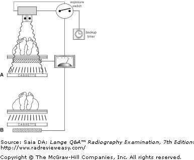
Which of the illustrations in the figure below depicts the ionization-chamber type of automatic exposure control?
A Figure a.
B Figure b.
C Both are ionization-chamber-type AEC.
D Neither is ionization-chamber-type AEC.
A Figure a.
-AEC devices are used in today's equipment and serve to produce consistent and comparable radiographic results. In one type of AEC, there is an ionization chamber just beneath the tabletop above the IR (A). The part to be examined is centered to the sensor and radiographed. When a predetermined quantity of ionization has occurred (equal to the correct receptor exposure), the exposure automatically terminates. In the other type of AEC, the phototimer, a small fluorescent screen is positioned beneath the IR (B). When remnant radiation emerging from the patient exits the IR, the fluorescent screen emits light. Once a predetermined amount of fluorescent light is "seen" by the photocell sensor, the exposure is terminated. A special IR, one without lead foil backing, is often required with this type of AEC. In either case, the manual timer should be used as a backup timer. In case of AEC malfunction, this would terminate the exposure, thus avoiding patient overexposure and tube overload.
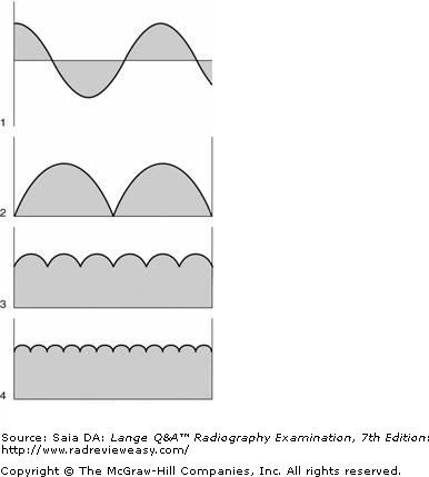
Which of the waveforms illustrated in the figure below represents single-phase, full-wave rectified equipment?
A Figure 1
B Figure 2
C Figure 3
D Figure 4
B Figure 2
-Four waveforms are illustrated. Number 1 represents unrectified alternating current, which has constantly changing amplitude and periodically changing polarity; only the positive half-cycle is useful. Number 2 represents single-phase, full-wave-rectified current; the negative half-cycle is rectified to a useful positive half-cycle. Numbers 3 and 4 represent three-phase rectified current; number 3 is 3-phase, 6-pulse, and number 4 is 3-phase, 12-pulse
A test pattern, such as the TG 18-CT test pattern, is used to qualitatively evaluate
A Radiographic film-screen contact
B The luminance response of a digital display monitor
C The X-ray exposure field alignment
D The exposure rate in an X-ray beam
B The luminance response of a digital display monitor
-The TG 18-CT test pattern is used to qualitatively evaluate the luminance response of a digital display monitor (B). Luminance response refers to the comparison of input to the display device and the actualdisplayed luminance value. The displayed luminance value varies between L min and L max and is impacted by ambient light as well (L amb ). The pattern in TG 18-CT testing device includes 16 low-contrast targets that should be visible on the display. The test pattern should be viewed from a distance of approximately 30 cm. One frequent observation is inability to visualize one or more shades in the darker regions. Radiographic film-screen (A) contact is evaluated by exposing a wire mesh screen on top of a conventional radiographic cassette holding an unexposed film. Any blurred areas of the wire mesh would indicate that there is poor film-screen contact in that particular area. The X-ray exposure field alignment (C) can be tested by using a square or rectangular leaded test pattern. An exposure is made with this test pattern device positioned on top of the receptor with collimator light field adjusted to match the size of the test pattern. The resultant image is then inspected to determine if the X-ray exposure field is congruent with the borders of the test pattern. The exposure rate (D) in an X-ray beam is measured with a calibrated radiation dosimeter that contains an ionization chamber or photodiode.
The continued emission of light by a phosphor after the activating source has ceased is termed
A fluorescence
B phosphorescence
C image intensification
D quantum mottle
B phosphorescence
-Fluorescence occurs when an intensifying screen absorbs x-ray photon energy, emits light, and then ceases to emit light as soon as the energizing source ceases. Phosphorescence occurs when an intensifying screen absorbs x-ray photon energy, emits light, and continues to emit light for a short time after the energizing source ceases. Quantum mottle is the freckle-like appearance on some radiographs made using a very fast imaging system. The brightness of a fluoroscopic image is amplified through image intensification.
Which of the following functions to increase the milliamperage?
A Increasing the speed of anode rotation
B Increasing the transformer turns ratio
C Using three-phase rectification
D Increasing the heat of the filament
D Increasing the heat of the filament
-The thoriated tungsten filament of the cathode assembly is heated by its own filament circuit. This circuit provides current and voltage to heat the filament to incandescence, at which time it undergoes thermionic emission (the liberation of valence electrons from filament atoms). The greater the number of electrons flowing between the cathode and the anode, the greater is the tube current (mA).Rectification (single- or three-phase) is the process of changing alternating current to unidirectional current. A greater number of secondary transformer turns functions to increase voltage and decrease current
Circuit devices that permit electrons to flow in only one direction are
A solid-state diodes
B resistors
C transformers
D autotransformers
A solid-state diodes
-Rectifiers change AC into unidirectional current by allowing current to flow through them in only one direction. Valve tubes are vacuum rectifier tubes found in older equipment. Solid-state diodes are the types of rectifiers used in today's x-ray equipment. Rectification systems are found between the secondary coil of the high-voltage transformer and the x-ray tube. Resistors, such as rheostats or choke coils, are circuit devices used to vary voltage or current. Transformers, operating on the principle of mutual induction, change the voltage (and current) to useful levels. Autotransformers, operating on the principle of self-induction, enable us to select the required kilovoltage.
The most common cause of x-ray tube failure is
A a cracked anode.
B a pitted anode.
C vaporized tungsten on glass envelope.
D insufficient heat production.
C vaporized tungsten on glass envelope.
-Excessive heat production is a major problem in x-ray production. Of the energy required to produce x-rays, 0.2% is transformed to x-rays, and 99.8% is transformed to heat. The copper anode stem and the oil surrounding the x-ray tube help to move heat away from the face of the anode. Excessive heat can cause pitting of the anode (resulting in decreased output) or actual cracking of the anode or damage to the rotor bearings (resulting in tube failure). As the cathode filament is heated for exposure after exposure, some of its tungsten is vaporized and deposited on the inner surface of the glass envelope near the tube window. After a time, this can cause electric arcing and tube failure. This is the most common cause of tube failure because it can occur even with normal use.
The x-ray imaging system that uses a flat panel detector is
A film emulsion system.
B computed radiography.
C direct digital radiography.
D fluoroscopy.
C direct digital radiography.
-Medical imaging is experiencing rapid technological growth, and x-ray images can be obtained in a number of ways. Film/screen systems are rarely used today. Imaging systems used today include computed radiography (CR) and direct digital radiography (DR). CR uses an Image Plate (IP) that encloses the photostimulable phosphor (PSP). When the PSP is exposed, it stores the image; a scanner-reader then converts the PSP image to a digital image; the image is then displayed on a computer monitor. Direct digital radiography (DR) eliminates the IP and PSP. The x-ray image is captured by a flat panel detector in the x-ray table and converts it to a digital image; the x-ray image is displayed immediately on a computer monitor. Fluoroscopy is a "live action" or "real-time" examination where the dynamics (motion) of parts can be evaluated; "still" images can be made during the fluoroscopic exam.

Referring to the simplified x-ray circuit shown in Figure 7–16, what is indicated by the number 4?
A Step-up transformer
B Kilovoltage meter
C Grounded milliamperage meter
D Rectification system
C Grounded milliamperage meter
-In the simplified x-ray circuit shown, the autotransformer is labeled number 1, the primary coil of the high-voltage transformer is number 2, and the secondary coil is labeled number 3. The autotransformer selects the voltage that will be sent to the high-voltage transformer to be stepped up to the thousands of volts required for x-ray production. At the midpoint of the secondary coil is the grounded milliamperage meter (number 4). Since the milliamperage meter is in the control panel and is associated with high voltage, it must be grounded. The rectification system, which is used to change alternating current to unidirectional current, is indicated by the number 5. The rectification system is located between the secondary coil of the high-voltage transformer (number 3) and the x-ray tube (number 7).
Advantages of high-frequency generators include
- small size
- decreased patient dose
- nearly constant potential
A 1 only
B 1 and 2 only
C 2 and 3 only
D 1, 2, and 3
D 1, 2, and 3
-Conventional 60-Hz full-wave rectified power is converted to a higher frequency of 500 to 25,000 Hz in the most recent generator design—the high-frequency generator. The high-frequency generator is small in size, in addition to producing an almost constant potential waveform. High-frequency generators first appeared in mobile x-ray units and were then adopted by mammography and CT equipment. Today, more and more radiographic equipment uses high-frequency generators. Their compact size makes them popular, and the fact that they produce nearly constant potential voltage helps to improve image quality and decrease patient dose (fewer low-energy photons to contribute to skin dose)
Which of the following artifacts is occasionally associated with the use of grids in digital imaging?
A Incomplete erasure
B Aliasing
C Image fading
D Vignetting
B Aliasing
-An artifact associated with digital imaging and grids is “aliasing” or the “moiré effect.” If the direction of the lead strips and the grid lines per inch (i.e., grid frequency) matches the scan frequency of the scanner/reader, this artifact can occur. Aliasing (or Moiré effect) appears as superimposed images slightly out of alignment, an image “wrapping” effect. This most commonly occurs in mobile radiography with stationary grids and can be a problem with DR flat panel detectors.
Electronic imaging terms used to indicate the intensity of radiation reaching the IR include
- exposure index
- sensitivity (S) number
- field of view (FOV)
A 1 only
B 1 and 2 only
C 2 and 3 only
D 1, 2, and 3
B 1 and 2 only
-Computed radiography (CR) offers wide latitude and automatic optimization of the radiologic image. When AEC is not used, CR can compensate for about 80% underexposure and 500% overexposure. This can be an important advantage in trauma and mobile radiography. The radiographer still must be vigilant in patient dose considerations—overexposure, though correctable, results in increased patient dose; underexposure results in decreased image quality owing to increased image noise. CR systems provide an exposure indicator: an S (sensitivity) number, exposure index EI, or other relative exposure index depending on the manufacturer used. The manufacturer usually provides a chart identifying the acceptable range the exposure indicator numbers should be within for various examination types. For example, a high S number often is related to underexposure, whereas a high EI number is related to overexposure. Field of view (FOV) refers to the anatomic area being visualized.
Dedicated radiographic units are available for
1.chest radiography.
2.dental radiography.
3.mammography.
A 1 only
B 2 only
C 1 and 2 only
D 1, 2, and 3
D 1, 2, and 3
-Special units have been designed to accommodate examinations with high patient volume. Dedicated chest units are available with high frequency generator and digital flat-panel detector. Dedicated head units are available for cone beam and panoramic digital dental imaging. High-quality mammographic examinations are available with dedicated mammographic units having molybdenum or rhodium target material and other beneficial features.
Magnification fluoroscopy provides:
A Decreased resolution and decreased patient dose
B Decreased resolution and increased patient dose
C Increased resolution and decreased patient dose
D Increased resolution and increased patient dose
D Increased resolution and increased patient dose
-Magnification fluoroscopy requires that a multifield image intensifier be used to allow reduction of the x-ray field size to the input phosphor area. Smaller input phosphor field sizes produce magnified images of the anatomical areas being evaluated at the output phosphor. Magnification fluoroscopy provides increased resolution, but at the expense of increased patient dosage (D). In fact, the increase in dosage is about 2.2 times that used in the full-field operation mode. The magnification mode should therefore be used only when necessary to enhance diagnostic interpretation of small anatomical areas in question (e.g., the gallbladder or duodenal bulb)
In Figure 5–8, what is the maximum safe milliamperage that may be used with a 0.10-s exposure and 120 kVp, using the 3-phase, 1.0-mm focal-spot x-ray tube?
A 300 mA
B 400 mA
C 500 mA
D 600 mA
A 300 mA
-A radiographic rating chart enables the radiographer to determine the maximum safe milliamperage, exposure time, and kilovoltage for a given exposure using a particular x-ray tube. Because the heat load that an anode will safely accept varies with the size of the focal spot, type of rectification, and anode rotation, these variables must also be identified. Each x-ray tube has its own characteristics and its own rating chart. Find the correct chart for the three-phase, 1.0-mm focal-spot x-ray tube. Locate 0.1 s on the horizontal (seconds) axis and follow it up to where it intersects with the 120-kVp line on the vertical (kVp) axis. They intersect just below the 300-mA curve, at approximately 310 mA. Thus, 300 mA is the maximum safe milliamperage for this particular group of exposure factors and x-ray tube.
The filtering effect of the x-ray tube's glass envelope and its oil coolant are referred to collectively as
A inherent filtration
B added filtration
C compensating filtration
D port filtration
A inherent filtration
-The x-ray photons emitted from the anode focus are heterogeneous in nature. The low-energy photons must be removed because they are not penetrating enough to contribute to the image and because they do contribute to the patient's skin dose. The glass envelope and oil coolant provide approximately 0.5- to 1.0-mm Al equivalent filtration, which is referred to as inherent because it is a built-in, permanent part of the tube head.
In digital imaging, the maximum spatial resolution is equal to:
A The Nyquist frequency, which is 1/2X the pixel pitch (mm)
B The wavelength of the detector system’s analog-to-digital converters electrical signal
C The distance between the silver halide crystals in the image receptor
D The detective quantum efficiency of the imaging system; this should be at least 2X the frequency of the analog-to-digital convertor electrical signal
A The Nyquist frequency, which is 1/2X the pixel pitch (mm)
-With digital systems, the spatial resolution is related to pixel pitch. The maximum spatial resolution is equal to the Nyquist frequency, 1/2X the pixel pitch (mm) (A). The wavelength of the electrical signal in an analog-to-digital convertor (ADC) is constant, and not affected by the pixel pitch of the matrix (B). Digital imaging does not use receptors with silver halide crystals. These crystals are used in radiographic film (C). Spatial resolution depends on the pixel sizes and pitch in the image matrix. Detective quantum efficiency (DQE) is a measure of the efficiency of a digital system to detect the X-ray photons and convert them into an image signal, regardless of the size and pitch of the image matrix pixels (D).
A quality-control (QC) program includes checks on which of the following radiographic equipment conditions?
- Reproducibility
- Linearity
- Positive beam limitation/automatic collimation
A 1 only
B 1 and 2 only
C 1 and 3 only
D 1, 2, and 3
D 1, 2, and 3
-The accuracy of all three is important to ensure adequate patient protection. Reproducibility means that repeated exposures at a given technique must provide consistent intensity. Linearity means that a given milliampere-seconds value, using different milliamperage stations with appropriate exposure time adjustments, will provide consistent intensity. PBL is automatic collimation and must be accurate to 2% of the SID. Light-localized collimators must be available and must be accurate to within 2%.
Congruence of the x-ray beam with the light field is tested using
A a pinhole camera
B a star pattern
C radiopaque objects
D a slit camera
C radiopaque objects
-Radiographic results should be consistent and predictable with respect to positioning accuracy, exposure factors, and equipment operation. X-ray equipment should be tested and calibrated periodically as part of an ongoing quality assurance (QA) program. The focal spot should be tested periodically to evaluate its size and its impact on spatial resolution; this is accomplished using a slit camera, a pinhole camera, or a star pattern. To test the congruence of the light and x-ray fields, a radiopaque object such as a paper clip or a penny is placed at each corner of the light field before the test exposure is made. Upon viewing, the corners of the x-ray field should be exactly delineated by the radioopaque objects.
An important feature of the pixel in a flat-panel TFT digital detector active matrix array is the:
A Nyquist frequency
B Fill factor
C Image lag
D Modulation transfer function
B Fill factor
-The fill factor (B) is defined as the ratio of the sensing area of the pixel to the area of the pixel itself. The sensing area of the pixel receives the data from the layer above it, which captures X-rays that are subsequently converted to light (indirect flat-panel detectors) or electrical charges (direct flat-panel detectors).
The Nyquist frequency (A) is 1/2X the pixel pitch (mm) and is equivalent to the spatial resolution in digital systems. A pixel contains generally three components: the TFT, the capacitor, and the sensing area. Image lag (C) is an undesirable phenomenon that refers to the persistence of the image, that is, a charge is still being produced in a digital detector after the radiation beam from the X-ray tube has been turned off. The modulation transfer function (D) is a mathematical function that measures the ability of the digital detector to transfer its spatial resolution characteristics to the image.
The term windowing describes the practice of
A varying the automatic brightness control
B changing the image contrast and/or brightness
C varying the FOV
D increasing resolution
B changing the image contrast and/or brightness
-In electronic imaging (CR/DR), the radiographer can manipulate the digital image displayed on the CRT through postprocessing. One way to alter image contrast and/or brightness is through windowing. This refers to some change made to window width and/or window level. Change in window width changes the number of gray shades, that is, image contrast. Change in window level changes the image brightness .Windowing and other post processing mechanisms permit the radiographer to produce “special effects” such as edge enhancement, image stitching, and image inversion, rotation, and reversal. A digital image is formed by a matrix of pixels in rows and columns. A matrix having 512 pixels in each row and column is a 512 × 512 matrix. The term field of view is used to describe how much of the patient (e.g., 150-mm diameter) is included in the matrix. The matrix or field of view can be changed without affecting the other, but changes in either will change pixel size. Automatic brightness control is associated with image intensification.
Which of the x-ray circuit devices shown in Figure 7–16 operates on the principle of self-induction?
- Number 1
- Number 2
- Number 3
A 1 only
B 1 and 2 only
C 2 and 3 only
D 1, 2, and 3
A 1 only
-The autotransformer (number 1) controls/selects the amount of voltage sent to the primary winding of the high-voltage transformer and operates on the principle of self-induction. The step-up (high-voltage)transformer (primary coil is number 2; secondary coil is number 3) operates on the principle of mutual induction. The step-up transformer functions to change low voltage to the high voltage necessary to produce x-ray photons. The x-ray tube is identified as number 7.
During CR imaging, the latent image present on the PSP is changed to a computerized image by the
A PSP
B Scanner–reader
C ADC
D helium–neon laser
C ADC
-The exposed CR cassette is placed into the CR scanner/reader, where the PSP (SPS) is removed automatically. The latent image appears as the PSP is scanned by a narrow, high-intensity helium–neon laser to obtain the pixel data. As the plate is scanned in the CR reader, it releases a violet light—a process referred to as photostimulated luminescence (PSL). The luminescent light is converted to electrical energy representing the analog image. The electrical energy is sent to an analog-to-digital converter (ADC), where it is digitized and becomes the digital image that is displayed eventually (after a short delay) on a high-resolution monitor and/or printed out by a laser printer. The digitized images can also be manipulated in postprocessing, transmitted electronically, and stored/archived.
The purpose of magnification fluoroscopy is to:
A Enhance the image in order to facilitate diagnostic interpretation
B Decrease patient dosage
C Decrease fluoroscopy time
D Increase efficiency of X-ray production
A Enhance the image in order to facilitate diagnostic interpretation
-Magnification of the image is an important feature of the image intensifier. The purpose of magnification fluoroscopy is to enhance the image in order to assist the radiologist in diagnostic interpretation (A). Magnification mode in fluoroscopy actually increases patient dosage (B), as more radiation is necessary to produce the brightness levels needed to view the images. The magnification mode should therefore be used only when necessary to enhance diagnostic interpretation of small specific anatomical areas in question. Fluoroscopy time should be limited in order to ensure the practice of ALARA. However, the time needed to evaluate the anatomical areas in question is not limited to a certain time (C). Magnification fluoroscopy neither increases or decreases fluoroscopic evaluation time. X-ray production efficiency is a function of the generator and X-ray tube providing the necessary X-ray energy to produce the fluoroscopic image. Magnification fluoroscopy, therefore, does not alter the efficiency of X-ray production (D).
Which of the following x-ray circuit devices operate(s) on the principle of mutual induction?
- High-voltage transformer
- Filament transformer
- Autotransformer
A 1 only
B 1 and 2 only
C 1 and 3 only
D 1, 2, and 3
B 1 and 2 only
-In mutual induction, two coils are in close proximity, and a current is supplied to one of the coils. As the magnetic field associated with every electric current expands and “grows up” around the first coil, it interacts with and “cuts” the turns of the second coil. This interaction, motion between magnetic field and coil (conductor), induces an electromotive force (emf) in the second coil. This is mutual induction,the production of a current in a neighboring circuit. Transformers, such as the high-voltage transformer and the filament (step-down) transformer, operate on the principle of mutual induction. The autotransformer operates on the principle of self-induction. Both the transformer and the autotransformer require the use of alternating current.
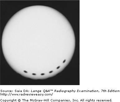
The radiograph illustrated in the figure below was made using a single-phase, full-wave-rectified unit with a timer and rectifiers that are known to be accurate and functioning correctly. What exposure time was used to produce this image?
A 1/10 second
B 0.05 second
C 1/12 second
D 0.025 second
B 0.05 second
-When a spinning top is used to test the timer efficiency of full-wave-rectified single-phase equipment, the result is a series of dots or dashes, with each dot representing a pulse of radiation. With full-wave-rectified current and a possible 120 dots (pulses) available per second, one should visualize 12 dots at 1/10 second, 6 dots at 0.05 second, 10 dots at 1/12 second, and 3 dots at 0.025 second. Because three-phase equipment is at almost constant potential, a synchronous spinning top must be used for timer testing, and the result is a solid arc (rather than dots). The number of degrees covered by the arc is measured and equated to a particular exposure time.
Incomplete erasure of CR plates can contribute to a
A Ghost artifact
B Moiré artifact
C Static artifact
D Grid cutoff artifact
A Ghost artifact
-The appearance of ghost artifacts (A) can be seen when CR image plates are incompletely erased. If an image plate has not been used for 24 hours, its phosphor storage plate should be erased again before using it for a diagnostic radiographic exposure. If a radiographic grid has a frequency that approximates the CR scan frequency and the grid strips are oriented in the same direction as the scan, the Moiré artifact may be observed (B); to decrease the possibility of this effect, high frequency grids are recommended for digital imaging. Grid cutoff artifacts (D) are seen as a decrease in receptor exposure on one side of the image when the CR is off-centered or not perpendicular to the grid – or, on both sides when the central ray is properly centered but the focal range is exceeded when using a focused grid. Static artifacts (C) may be seen on radiographic film imaging.
The advantages of high-frequency generators over earlier types of generators include
- smaller size.
- nearly constant potential.
- lower patient dose.
A 1 only
B 1 and 2 only
C 1 and 3 only
D 1, 2 and 3
D 1, 2 and 3
-High-frequency generators first appeared in mobile x-ray units and were then adopted by mammography and CT equipment. Today, more and more radiographic equipment uses high-frequency generators. Their compact size makes them popular, and the fact that they produce nearly constant potential voltage helps to improve image quality and decrease patient dose (fewer low-energy photons to contribute to skin dose).
Too much edge enhancement of the image in digital systems can cause an unwanted artifact called the:
A Photoelectric effect artifact
B Scaling artifact
C Hounsfield artifact
D Halo effect artifact
D Halo effect artifact
-One of the problems seen with too much edge enhancement is an effect called the “halo” effect (D). This effect can cause loss of anatomical information and artifacts that may interfere with proper diagnoses. The photoelectric effect (A) occurs when an X-ray photon interacts with an inner shell electron of an atom and its energy is completely absorbed by the atom. This interaction is responsible for producing diagnostic information in a radiographic image and contributing to patient dosage. A scaling artifact is not an artifact seen in digital imaging (B). A Hounsfield artifact is not an artifact seen in digital imaging (C).
Which of the following mobile radiography applications enables the radiographer to view the radiographic image before leaving the patient?
A Fixed digital units of any type
B Tethered or wireless flat-panel digital mobile units
C Portable units using conventional radiographic film
D Battery operated conventional radiography mobile units
B Tethered or wireless flat-panel digital mobile units
-Detectors in mobile digital units may use either tethered or wireless flat-panels (B), which allows the radiographer to view the radiographic image at the patient’s bedside. An acceptable image may then be sent to a PACS system for physician review. Fixed digital units (A) are found in the radiology department and cannot be used for mobile applications. Portable units using conventional radiographic film (C) requires the radiographer to chemically process the film in a darkroom located in the radiology department. Battery operated conventional radiography mobile units (D) are used with conventional radiographic film and, therefore, the film must be chemically processed in the darkroom located in the radiology department.
As the CR laser scanner/reader recognizes the phosphostimulated luminescence (PSL) released by the PSP storage plate, it constructs a graphic representation of pixel value distribution called a
A processing algorithm
B histogram
C lookup table
D exposure index
B histogram
-As the CR laser scanner/reader recognizes the phosphostimulated luminescence (PSL) released by the PSP storage plate, it constructs a graphic representation of pixel value distribution called a histogram.
The photostimulable storage phosphor (PSP) within the IP is the image receptor (IR). The PSP is a europium-doped barium fluorohalide coated storage plate. When the PSP is exposed by x-ray photons, the x-ray energy interacts with the crystals and a small amount of visible light is emitted, but most of the x-ray energy is stored (hence, the term storage plate). This stored energy represents the latent image.
The IP is placed in the CR scanner/reader where a helium–neon, or solid-state, laser beam scans the PSP and its stored energy is released as blue-violet light (phosphostimulated luminescence [PSL]). This light signal represents varying tissue densities and the latent image that is then transferred to an analog-to-digital converter (ADC)—converting the signal to a digital (electrical) one.
The PSL values will result in numerous image brightness values that represent various tissue densities(i.e., x-ray attenuation properties), for example, bone, muscle, blood-filled organs, air/gas, pathologic processes, and so on. The CR scanner/reader recognizes all these values and constructs a representative gray-scale histogram of them corresponding to the anatomical characteristics of the imaged part. Thus, all PA chest histograms will be similar, all lateral chest histograms will be similar, all pelvis histograms will be similar, and so on.
A histogram is a graphic representation of pixel-value distribution. The histogram analyzes all the densities from the PSP and represents them graphically—demonstrating the quantity of exposure, the number of pixels, and their value. Histograms are generated that are unique to each body part that can be imaged.
After a part is exposed/imaged, its PSP is read/scanned and its own histogram is developed and analyzed. The resulting analysis, and histogram of the actual imaged part, is compared to the programmed representative histogram for that part. Over time, if required diagnostic image characteristics change, a histogram can be updated to reflect the latest required characteristics
In conventional fluoroscopy, all of the following are methods of permanently recording the images, except:
A Cassette-loaded spot film
B Photospot camera film
C Cine film
D Flat panel image receptor
D Flat panel image receptor
-A flat panel image receptor (FPIR) (D) composed of cesium iodide and amorphous silicon pixel detectors can be used in place of an image intensifier in digital fluoroscopy for real-time imaging. Images created from this device are digitized and therefore can be stored in a PACS, but this device is not considered a recording system in itself. It only generates the image to be recorded. A cassette-loaded spot film (A) is positioned in a lead-lined compartment between the patient and the image intensifier. When a spot-film exposure is desired, the radiologist must actuate a control that properly positions the cassette in the X-ray beam and changes the operation of the X-ray tube from low fluoroscopic milliamperes (mA) to high radiographic mA, at which time the rotating anode is energized to a higher rotation speed.Photospot camera film (B) is similar to a movie camera except only one frame is exposed when activated. This film receives its light image from the output phosphor of the image intensifier tube and therefore requires less patient exposure than that required when using the cassette-loaded spot film image recording method. Cine film is almost exclusively used in cardiac catheterization fluoroscopic procedures. Cine film (C) typically comes in 35 mm rolls of 100 and 500 feet in length and is exposed by the light from the output phosphor of the image intensifier tube, similar to that of the photospot camera film, but while rapidly moving to expose each frame of the film strip. The exposed frames can then be played back as a continuous strip of images to produce a dynamic reproduction of the fluoroscopic images, similar to how one would draw various, slightly different images, on the same spot on multiple blank pieces of paper, and then flip these pieces of paper rapidly to produce what appears to be a moving image. Because of the rapid transition to digital imaging, the use of cine film is rapidly declining.
The radiograph shown in Figure 5–5 was made using a
A three-phase, 6-pulse rectified unit
B three-phase, 12-pulse rectified unit
C single-phase, full-wave rectified unit
D high-frequency rectified unit
C single-phase, full-wave rectified unit
-A spinning top is used to test the timer efficiency of full-wave-rectified single-phase equipment. The result should be a series of dots or dashes, with each dot representing a pulse of x-radiation. With full-wave-rectified current there should be 120 dots/pulses seen per second. One should visualize 12 dots/pulses at 1 / 10 s, 6 dots at 0.05 s, 10 dots at 1 / 12 s, and 3 dots at 0.025 s. If an incorrect number of dots/pulses is obtained, it is an indication of either timer malfunction or rectifier failure. Because three-phase equipment is at almost constant potential, a synchronous spinning top must be used for timer testing, and the result is a solid arc (rather than dots). The number of degrees covered by the arc is measured and equated to a particular exposure time; one second exposure should demonstrate 360 degrees.
As the image intensifier's FOV is reduced, how is the resulting image affected?
1.Magnification increases
2.Brightness decreases
3.Quality increases
A 1 only
B 1 and 2 only
C 2 and 3 only
D 1, 2, and 3
D 1, 2, and 3
-As voltage is applied to the electrostatic focusing lenses, the focal point moves back—closer to the input phosphor—and, as a result, the FOV decreases and magnification increases. At the same time, brightness is decreased requiring an increase in mA (therefore increased patient dose). This increase in mA increases image quality—it can be likened to an increase in signal-to-noise ratio (SNR), with mA being the signal.
The housing surrounding an x-ray tube functions to
- retain heat within the glass envelope
- protect from electric shock
- keep leakage radiation to a minimum
A 1 and 2 only
B 1 and 3 only
C 2 and 3 only
D 1, 2, and 3
C 2 and 3 only
-When high-speed electrons strike surfaces other than the tungsten target, x-rays may be produced and emitted in all directions. X-ray tubes, therefore, have a lead-lined metal protective housing to absorb much of this “leakage radiation.” Leakage radiation must not exceed 100 mR/h at a distance of 1 m from the tube. Because the production of x-radiation requires the use of exceedingly high voltage, the tube housing also serves to protect from electric shock. The production of x-rays involves the production of large quantities of heat, which can be damaging to the x-ray tube. Therefore, an oil coolant surrounds the x-ray tube to further insulate it and to absorb heat from the x-ray tube structures.
Off-focus and scatter radiation outside of the exposure field when using CR can cause:
A Narrowing of the histogram
B Widening of the histogram
C Improper alignment of the exposure field
D High contrast
B Widening of the histogram
-Off-focus and scatter radiation outside of the exposure field would be detected as additional information and, therefore, would widen the histogram (B), resulting in a processing error. Histogram analysis errors can result in rescaling errors and exposure indicator determination errors. Alignment of the exposure field (C) is set by the radiographer prior to the exposure. Any off-focus and scatter radiation exposure outside of the exposure field will not change this alignment. Scatter radiation decreases image contrast (D).
Which of the following is (are) correct regarding care of protective leaded apparel?
- Lead aprons should be fluoroscoped yearly to check for cracks.
- Lead gloves should be fluoroscoped yearly to check for cracks.
- Lead aprons should be hung on appropriate racks when not in use.
A 1 only
B 1 and 2 only
C 1 and 3 only
D 1, 2, and 3
D 1, 2, and 3
-Proper care of leaded protective apparel is required to ensure its continued usefulness. If lead aprons and gloves are folded, cracks will develop, and this will decrease their effectiveness. Both items should be fluoroscoped annually to check for the formation of cracks.
Excessive anode heating can cause vaporized tungsten to be deposited on the port window. This can result in
1.decreased tube output.
2.tube failure.
3.electrical sparking.
A 1 only
B 2 only
C 1 and 2 only
D 1, 2, and 3
D 1, 2, and 3
-Vaporized tungsten may be deposited on the inner surface of the glass envelope at the tube (port) window. It acts as an additional filter, thereby reducing tube output. The tungsten deposit may also attract electrons from the filament, creating sparking and causing puncture of the glass envelope and subsequent tube failure.
The brightness level of the fluoroscopic image can vary with
- milliamperage
- kilovoltage
- patient thickness
A 1 only
B 1 and 2 only
C 1 and 3 only
D 1, 2, and 3
D 1, 2, and 3
-The thicker and more dense the anatomic part being studied, the less bright will be the fluoroscopic image. Both milliamperage and kilovoltage affect the fluoroscopic image in a way similar to the way in which they affect the radiographic image. For optimal contrast, especially taking patient dose into consideration, higher kilovoltage and lower milliamperage are generally preferred.
Which of the following x-ray circuit devices operate(s) on the principle of mutual induction?
1.High-voltage transformer
2.Filament transformer
3.Autotransformer
A 1 only
B 1 and 2 only
C 1 and 3 only
D 1, 2, and 3
B 1 and 2 only
-In mutual induction, two coils are in close proximity, and a current is supplied to one of the coils. As the magnetic field associated with every electric current expands and "grows up" around the first coil, it interacts with and "cuts" the turns of the second coil. This interaction, motion between magnetic field and coil (conductor), induces an emf in the second coil. This is mutual induction, the production of a current in a neighboring circuit. Transformers such as the high-voltage transformer and the filament (step-down) transformer operate on the principle of mutual induction. The autotransformer operates on the principle of self-induction. Both the transformer and the autotransformer require the use of alternating current.
The AEC device operates on which of the following principles?
1.Delivery of the required exposure time
2.A parallel-plate ionization chamber charged by x-ray photons
3.Motion of magnetic fields inducing current in a conductor
A 1 only
B 2 only
C 1 and 2 only
D 1, 2, and 3
C 1 and 2 only
-A parallel-plate ionization chamber is the most commonly used AEC. A radiolucent chamber is beneath the patient (between the patient and the IR). As photons emerge from the patient, they enter the chamber and ionize the air within it. Once a predetermined charge has been reached, the exposure is automatically terminated. AEC determines exposure time; the radiographer must determine optimum kV and mA. Motion of magnetic fields inducing a current in a conductor refers to the principle of mutual induction.
Which part of an induction motor is located within the x-ray tube glass envelope?
A Filament
B Focusing cup
C Stator
D Rotor
D Rotor
-The anode is made to rotate through the use of an induction motor. An induction motor has two main parts, a stator and a rotor. The stator is the part located outside the glass envelope and consists of a series of electromagnets occupying positions around the stem of the anode. The stator's electromagnets are supplied with current, and the associated magnetic fields function to exert a drag or pull on the rotor within the glass envelope. The anode is a 2- to 5-in.-diameter molybdenum or graphite disk with a beveled edge. The beveled surface has a focal track of tungsten and rhenium alloy. The anode rotates at about 3,600 rpm (high-speed anode rotation is about 10,000 rpm) so that heat generated during x-ray production is distributed evenly over the entire track. Rotating anodes can withstand delivery of a greater amount of heat for a longer period of time than stationary anodes.
Of what material is the x-ray tube component numbered 2 in Figure 7–18 made?
A Cesium
B Copper
C Nickel
D Tungsten
C Nickel
-The figure illustrates the x-ray tube component parts. Number 1 indicates the thoriated tungsten filament, which functions to release electrons when heated. Number 2 is the nickel focusing cup, which directs these electrons toward the anode's focal track. Number 4 is the rotating anode, and number 5 is the anode's focal track. The focal track is made of thoriated (for extra protection from heat) tungsten. When high-speed electrons are suddenly decelerated at the target, their kinetic energy is changed to x-ray photon energy.
A type of laser used in CR scanners is
A Cesium-iodide
B Helium-halide
C Barium-fluorohalide
D Helium-neon
D Helium-neon
-Cesium iodide (A) is used in the scintillation layer of an indirect flat-panel digital detector (FPD). Helium halide (B) is not used in either computed or digital radiography. Barium fluorohalide (C) is a phosphor used in the CR PSPs which are housed within the image plate (IP). Energy is stored in a PSP plate after X-ray exposure and is then released in the CR reader when stimulated by a helium-neon laser (D) beam striking it in a raster pattern (transversely across the plate). In some newer units, solid-state laser diodes may be used to achieve the same purpose.
Which of the following combinations would pose the most hazard to a particular anode?
A 0.6 mm focal spot, 75 kVp, 30 mAs
B 0.6 mm focal spot, 85 kVp, 15 mAs
C 1.2 mm focal spot, 75 kVp, 30 mAs
D 1.2 mm focal spot, 85 kVp, 15 mAs
A 0.6 mm focal spot, 75 kVp, 30 mAs
-Radiographic rating charts enable the operator to determine the maximum safe mA, exposure time, and kVp for a particular exposure using a particular x-ray tube. An exposure that can be made safely with the large focal spot may not be safe for use with the small focal spot of the same x-ray tube. The total number of HU that an exposure generates also influences the amount of stress (in the form of heat) imparted to the anode. The product of mAs and kVp determines HU. Groups A and C produce 2250 HU; groups B and D produce 1275 HU. Groups B and D deliver less heat load, but group D delivers it to a larger area (actual focal spot) making this the least hazardous group of technical factors. The mosthazardous group of technical factors is group A because it delivers the greatest heat (2,250 HU) with the small focal spot.
All the following statements regarding three-phase current are true except
A three-phase current is constant-potential direct current.
B three-phase equipment produces more x-rays per milliampere-second.
C three-phase equipment produces higher-average-energy x-rays than single-phase equipment.
D the three-phase waveform has less ripple than the single-phase waveform.
A three-phase current is constant-potential direct current.
-Three-phase current is obtained from three individual alternating currents superimposed on, but out of step with, one another by 120 degrees. The result is an almost constant potential current, with only a very small voltage ripple (4%–13%), producing more x-rays per milliampere-second.
The collimator light and actual irradiated area must be accurate to within what percentage of the SID?
A 2%
B 5%
C 10%
D 15%
A 2%
-Restriction of field size is one important method of patient protection. However, the accuracy of the light field must be evaluated periodically as part of a QA program. Guidelines set forth for patient protection state that the collimator light and actual irradiated area must be accurate to within 2% of the SID.
Which of the following is a device that can be used in lieu of an image intensifier/charge-coupled device combination in digital fluoroscopy?
A Charge-coupled device
B Flat panel image receptor
C photometer
D photomultiplier tube
B Flat panel image receptor
-A flat panel image receptor (FPIR) (B) composed of cesium iodide and amorphous silicon pixel detectors can be used in place of an image intensifier in digital fluoroscopy. There are several advantages of FPIR imaging over image intensifier/CCD imaging, including distortion free images, constant image quality and contrast resolution over the entire image, high detective quantum efficiency (DQE) at all dose levels, a rectangular image area coupled to a similar shaped image monitor, and its immunity to external magnetic fields. A charge-coupled device (CCD) (A) is mounted on the output phosphor of the image intensifier tube and is coupled via fiber optics or a lens system. The sensitive layer of crystalline silicon within the CCD responds to the light from the output phosphor, creating and electrical charge. The charges are sampled, pixel by pixel, and then manipulated to produce a digital image. A photometer(C) is used to measure the luminance response and uniformity of monitors used in digital imaging. A photomultiplier tube receives light energy from the scanned IP plate in a CR reader and converts it into an electrical (analog) signal that can then be converted to a binary signal in the analog-to-digital convertor (ADC). This binary signal is then processed by a computer to develop a diagnostic image. Newer CR readers may use a charged-coupled device (CDC) (D) to convert the light energy into an electrical signal.
IRs/cassettes frequently have a lead-foil layer behind the rear screen that functions to
A improve penetration
B absorb backscatter
C preserve resolution
D increase the screen speed
B absorb backscatter
-Many cassettes/IRs have a thin lead-foil layer behind the rear screen to absorb backscattered radiation that is energetic enough to exit the rear screen, strike the metal back, and bounce back to fog the image. When this happens, the IR's metal hinges or straps may be imaged in high-kilovoltage radiography. The lead foil absorbs the backscatter before it can fog the film.
The device used to change alternating current to unidirectional current is
A a capacitor
B a solid-state diode
C a transformer
D a generator
B a solid-state diode
-Some x-ray circuit devices, such as the transformer and autotransformer, will operate only on AC. The efficient operation of the x-ray tube, however, requires the use of unidirectional current, so current must be rectified before it gets to the x-ray tube. The process of full-wave rectification changes the negative half-cycle to a useful positive half-cycle. An x-ray circuit rectification system is located between the secondary coil of the high-voltage transformer and the x-ray tube. Rectifiers are solid-state diodes made of semiconductive materials such as silicon, selenium, or germanium that conduct electricity in only one direction. Thus, a series of rectifiers placed between the transformer and x-ray tube function to change AC to a more useful unidirectional current.
To determine how quickly an x-ray tube will disperse its accumulated heat, the radiographer uses a(n)
A technique chart.
B radiographic rating chart.
C anode cooling curve.
D spinning top test.
C anode cooling curve.
-An anode cooling curve identifies how many HU the anode can accommodate and the length of time required for adequate cooling between exposures. A radiographic rating chart is used to determine if the selected mA, exposure time, and kVp are within safe tube limits. A technique chart is used to determine the correct exposure factors for a particular part of the body of a given thickness. A spinning top test is used to test for timer inaccuracy or rectifier failure.

In the radiographic rating charts shown in Figure 5–8, what is the maximum safe kilovoltage that may be used with the 1.0-mm focal-spot, single-phase x-ray tube using 400 mA and a 0.02-s exposure?
A 70 kVp
B 75 kVp
C 80 kVp
D 85 kVp

C 80 kVp
-A radiographic rating chart enables the radiographer to determine the maximum safe milliamperage, exposure time, and kilovoltage for a given exposure using a particular x-ray tube. Because the heat load that an anode will safely accept varies with the size of the focal spot, type of rectification, and anode rotation, these variables must also be identified. Each x-ray tube has its own characteristics and its own rating chart. First, find the chart with the identifying single-phase sine wave in the upper right corner and the correct focal-spot size in the upper left corner (chart C). Once the correct chart has been identified, locate 0.02 s on the horizontal axis, and follow its line up to where it intersects with the 400-mA curve. Then draw a line to where this point meets the vertical (kVp) axis; it intersects at exactly 80 kVp. This is the maximum permissible kilovoltage exposure at the given milliampere-seconds for this x-ray tube. The radiographer should always use somewhat less than the maximum exposure.
To maintain image clarity, the path of electron flow from photocathode to output phosphor is controlled by
A the accelerating anode
B electrostatic lenses
C the vacuum glass envelope
D the input phosphor
B electrostatic lenses
-The input phosphor of an image intensifier receives remnant radiation emerging from the patient and converts it to a fluorescent light image. Directly adjacent to the input phosphor is the photocathode,which is made of a photoemissive alloy (usually a cesium and antimony compound). The fluorescent light image strikes the photocathode and is converted to an electron image. The electrons are carefully focused, to maintain image resolution, by the electrostatic focusing lenses, through the accelerating anode and to the output phosphor for conversion back to light.
TV camera tubes used in image intensification, such as the Plumbicon and Vidicon, function to
A increase the brightness of the input-phosphor image.
B transfer the output-phosphor image to the TV monitor.
C focus and accelerate electrons toward the output phosphor.
D record the output-phosphor image on the IR.
B transfer the output-phosphor image to the TV monitor.
-Image intensification is a process that converts the dim fluoroscopic image into a much brighter image, much like normal daylight. As x-ray photons emerge from the patient and enter the image intensifier, they first encounter the input phosphor, which is generally composed of cesium iodide phosphors. At the input phosphor, x-ray photons are converted to light photons, which, in turn, strike the photocathode. The photocathode is a photoemissive metal (usually antimony and cesium compounds); when struck by light, it emits electrons in proportion to the intensity of the light striking it. The electrons then are directed to the output phosphor via the electrostatic focusing lenses, speeded up in the neck of the tube by the accelerating anode and directed to the output phosphor for further amplification. Most image intensifiers offer brightness gains of 5,000–20,000. From the output phosphor, the image is taken by the TV camera, most often a Plumbicon or Vidicon tube, and transferred to the TV monitor.
Which of the following combinations would pose the least hazard to a particular anode?
A 0.6-mm focal spot, 75 kVp, 30 mAs
B 0.6-mm focal spot, 85 kVp, 15 mAs
C 1.2-mm focal spot, 75 kVp, 30 mAs
D 1.2-mm focal spot, 85 kVp, 15 mAs
D 1.2-mm focal spot, 85 kVp, 15 mAs
-Radiographic rating charts enable the operator to determine the maximum safe milliamperage, exposure time, and peak kilovoltage for a particular exposure using a particular x-ray tube. An exposure that can be made safely with the large focal spot may not be safe for use with the small focal spot of the same x-ray tube. The total number of heat units that an exposure generates also influences the amount of stress (in the form of heat) imparted to the anode. The product of milliampere-second and peak kilovolts determines HU. Groups (A) and (C) produce 2250 HU; groups (B) and (D) produce 1275 HU. Groups (B) and (D) deliver less heat load, but group (D) delivers it to a larger area (actual focal spot), making this the least hazardous group of technical factors. The most hazardous group of technical factors is group (A).
Histogram data that is skewed relative to the values of interest (VOI) of the histogram analysis used for a particular exam may be caused by all of the following, except:
A Anatomical structures not centered to the IP
B Excessive windowing
C The X-ray beam is not correctly aligned to the edges of the IP
D The beam edge is irregular because of overlap of a radiopaque shadow, such as a gonadal shield
B Excessive windowing
-Windowing (B) is a post-processing method of adjusting the brightness and contrast in the digital image. Histogram analysis errors occur prior to post-processing of the image. There are two types of windowing: level and width. Window level adjusts the overall image brightness. When the window level is increased, the image becomes darker. When decreased, the image becomes brighter. Window width adjusts the ratio of white to black, thereby changing image contrast. Narrow window width provides higher contrast (short-scale contrast), whereas wide window width will produce an image with less contrast (long-scale contrast). Answers A, C and D can cause histogram data to be skewed relative to the values of interest (VOI) of the histogram analysis used for a particular exam.
The device that receives the remnant beam, converts it into light, and then increases the brightness of that light is the
A charge-coupled device (CCD)
B spot camera
C image intensifier
D television monitor
C image intensifier
-The visual apparatus that is responsible for visual acuity and contrast perception is the cones within the retina. Cones are also used for daylight vision. Therefore, the most desirable condition for fluoroscopic viewing is to have a bright enough image to permit cone (daylight) vision for better perception of anatomic details. The image intensifier accomplishes this. The intensified image is then transferred to a TV monitor for viewing. Spot cameras record fluoroscopic events.
All the following statements regarding mobile radiographic equipment are true except
A the exposure cord must permit the operator to stand at least 6 ft from the patient, x-ray tube, and useful beam
B exposure switches must be the two-stage type
C a lead apron should be carried with the unit and worn by the radiographer during exposure
D the radiographer must alert individuals in the area before making the exposure
B exposure switches must be the two-stage type
-NCRP Report No. 102 states that the exposure switch on mobile radiographic units shall be so arranged that the operator can stand at least 2 m (6 ft) from the patient, the x-ray tube, and the useful beam. An appropriately long exposure cord accomplishes this requirement. The fluoroscopic and/or radiographic exposure switch or switches must be of the “dead man” type; that is, the exposure will terminate should the switch be released. A lead apron should be carried with every mobile x-ray unit for the operator to wear during the exposure. Lastly, the radiographer must be certain to alert individuals in the area, enabling unnecessary occupants to move away, before making the exposure.
Which of the following is (are) tested as part of a QC program?
- Beam alignment
- Reproducibility
- Linearity
A 1 only
B 1 and 2 only
C 1 and 3 only
D 1, 2, and 3
D 1, 2, and 3
-Each of the three is included in a good QC program. The QC deals with imaging equipment. (QA deals with people and management practices.) Beam alignment must be accurate to 2% of the SID.Reproducibility means that repeated exposures at a given technique must provide consistent intensity.Linearity means that a given milliampere-seconds value, using different milliamperage stations with appropriate exposure-time adjustments, will provide consistent intensity.
The safe approach to avoid an exposure field recognition error when using CR is to:
A Expose one image on the smallest IP available with collimation margins aligned parallel to the edges of the IP
B Expose multiple images on one IP, but make sure all collimation margins overlap
C Expose one image on the IP, but do not collimate
D Expose multiple images on one IP, but make sure all collimation margins are parallel to each other and do not overlap
A Expose one image on the smallest IP available with collimation margins aligned parallel to the edges of the IP
-The safe approach to avoid an exposure field recognition error when using CR is to acquire one image on the smallest IP available. Collimation margins should also be parallel to the edges of the cassette (A). Exposing multiple images on one image plate (B) with overlapping collimation borders can result in an exposure field recognition error. The ALARA principle should be applied for every radiographic exposure. Collimation is critical to minimize patient exposure and dose (C). It is best to expose one image on the smallest image plate that will include all pertinent anatomy. Making multiple exposures on one image plate, regardless of attention to proper collimation can result in an exposure field recognition error (D).
Which of the following devices converts electrical energy to mechanical energy?
A Motor
B Generator
C Stator
D Roto
A Motor
-A motor is the device used to convert electrical energy to mechanical energy. The stator and rotor are the two principal parts of an induction motor. A generator converts mechanical energy into electrical energy.
Which of the following combinations would deliver the least amount of heat to the anode of a three-phase, 12-pulse x-ray unit?
A 400 mA, 0.12 s, 90 kVp
B 300 mA, ½ s, 70 kVp
C 500 mA, 1/30 s, 85 kVp
D 700 mA, 0.06 s, 120 kVp
The Correct Answer is: C
Radiographic rating charts enable the
operator to determine the maximum safe milliamperage, exposure time,
and kilovoltage for a particular exposure using a particular x-ray
tube. An exposure that can be made using the large focal spot may not
be safe when the small focal spot of the same x-ray tube is used. The
total number of heat units an exposure generates also influences the
amount of stress (in the form of heat) imparted to the anode.
Single-phase heat units are determined by the product of
milliampere-seconds and kilovoltage. A correction factor is required
to determine the HU of three-phase equipment and high
frequency equipment. Unless the equipment manufacturer specifies
otherwise, three-phase and high frequency equipment heat units are
determined by multiplying mA × second × kV × 1.4. In the examples
given, then, group (A) produces 6,048 HU, group (B) produces 14,700
HU, group (C) produces 1,983 HU, and group (D) produces 7,056 HU.
Therefore, group (C) exposure factors will deliver the least amount of
heat to the anode.
The functions of a picture archiving and communication system (PACS) include
- storage of analog images
- retrieval of digital images
- storage of digital images
A 1 only
B 1 and 2 only
C 2 and 3 only
D 1, 2, and 3
C 2 and 3 only
-PACS refers to a picture archiving and communication system. Analog images (conventional images) can be digitized with a digitizer. PACS systems receive digital images and display them on monitors for interpretation. These systems also store images and allow their retrieval at a later time.
What is the function of the x-ray tube component numbered 2 in Figure 7–18?
A To release electrons when heated
B To release light when heated
C To direct electrons to the focal track
D To direct light to the focal track
C To direct electrons to the focal track
-The figure illustrates the x-ray tube component parts. Number 1 indicates the thoriated tungsten filament, which functions to release electrons when heated. Number 2 is the molybdenum focusing cup, which directs these electrons toward the anode's focal track. Number 4 is the rotating anode, and number 5 is the anode's focal track. The focal track is made of thoriated (for extra protection from heat) tungsten. When high-speed electrons are suddenly decelerated at the target, their kinetic energy is changed to x-ray photon energy.
The movement of the IP through the transport system of a CR reader is referred to as the:
A Slow-scan direction
B Charge-coupled direction
C Nyquist direction
D Fast-scan direction
A Slow-scan direction
-The IP moves slowly through the transport system of a CR reader and this movement is considered the slow-scan direction (A). The laser light in the reader is rapidly reflected by an oscillating polygonal mirror that redirects the beam through a special lens called the f-theta lens, which focuses the light on a cylindrical mirror that reflects the light toward the PSP (photostimulable phosphor). This light moves back and forth very rapidly to scan the PSP transversely, in a raster pattern, and this movement of the laser beam across the PSP is therefore called the fast-scan direction (D). Charge-coupled direction (B) is not a term used to describe laser scanning in the CR reader. Charge-coupled devices are used in digital image receptors. Nyquist direction (C) is not a term used to describe laser scanning in the CR reader. With digital systems, the spatial resolution is related to pixel pitch. The maximum spatial resolution is equal to the Nyquist frequency, or 1/2X the pixel pitch (mm)
Which of the following combinations would pose the least hazard to a particular anode?
A 1.2-mm focal spot, 92 kVp, 1.5 mAs
B 0.6-mm focal spot, 80 kVp, 3 mAs
C 1.2-mm focal spot, 70 kVp, 6 mAs
D 0.6-mm focal spot, 60 kVp, 12 mAs
A 1.2-mm focal spot, 92 kVp, 1.5 mAs
-Radiographic rating charts enable the operator to determine the maximum safe milliamperage, exposure time, and kilovoltage for a particular exposure using a particular x-ray tube. An exposure that can be made safely with the large focal spot may not be safe for use with the small focal spot of the same x-ray tube. The total number of heat units that an exposure generates also influences the amount of stress (in the form of heat) imparted to the anode. The product of milliampere-seconds and kilovoltage determines heat units. Group (A) produces 138 HU, group (B) produces 240 HU, group (C) produces 420 HU, and group (D) produces 720 HU. The least hazardous group of technical factors is, therefore, group (A). Group (A) is also delivering its heat to the large focal spot, thereby decreasing the heat load to the anode.
Which of the following devices is used to control voltage by varying resistance?
A Autotransformer
B High-voltage transformer
C Rheostat
D Fuse
C Rheostat
-The autotransformer operates on the principle of self-induction and functions to select the correct voltage to be sent to the high-voltage transformer to be “stepped up” to kilovoltage. The high-voltage transformer increases the voltage and decreases the current. The rheostat is a type of variable resistor that is used to change voltage or current values. It is found frequently in the filament circuit. A fuse is a device used to protect the circuit elements from overload by opening the circuit in the event of a power surge.
A star pattern is used to measure
1.focal spot resolution.
2.scatter resolution.
3.SID resolution.
A 1 only
B 1 and 2 only
C 1 and 3 only
D 1, 2, and 3
A 1 only
-A quality control program requires the use of a number of devices to test the efficiency of various components of the imaging system. A star pattern is a resolution testing device that is used to test the effect of focal spot size.
Changes between the images shown in the figures below represent changes made to
A pixel size
B matrix size
C window width
D window level
C window width
-The radiographer can manipulate (i.e., change or enhance) digital images displayed on the CRT throughpostprocessing. One way to alter image contrast and/or brightness is through windowing. The term windowing refers to some change made to window width and/or window level. Change in window width affects change in the number of gray shades, that is, image contrast—as demonstrated in the figures shown. Change in window level affects change in the image brightness . Windowing and other post processing mechanisms permit the radiographer to effect changes in the image and to produce “special effects” such as edge enhancement, image stitching (useful in scoliosis examinations), image inversion, rotation, and reversal.
Characteristics of the metallic element tungsten include
- ready dissipation of heat
- high melting point
- high atomic number
A 1 only
B 1 and 2 only
C 2 and 3 only
D 1, 2, and 3
D 1, 2, and 3
-The x-ray anode may be a molybdenum disk coated with a tungsten–rhenium alloy. Because tungsten has a high atomic number (74), it produces high-energy x-rays more efficiently. Since a great deal of heat is produced at the target, tungsten's high melting point (3,410°C) helps to avoid damage to the target surface. Heat produced at the target should be dissipated readily, and tungsten's conductivity is similar to that of copper. Therefore, as heat is applied to the focus, it can be conducted throughout the disk to equalize the temperature and thus avoid pitting, or localized melting, of the focal track.
A three-phase timer can be tested for accuracy using a synchronous spinning top. The resulting image looks like a
A series of dots or dashes, each representative of a radiation pulse
B solid arc, with the angle (in degrees) representative of the exposure time
C series of gray tones, from white to black
D multitude of small, mesh-like squares of uniform sharpness
B solid arc, with the angle (in degrees) representative of the exposure time
-When a spinning top is used to test the efficiency of a single-phase timer, the result is a series of dots or dashes, with each representing a pulse of radiation. With full-wave-rectified current and a possible 120 dots (pulses) available per second, one should visualize 12 dots at 1/10 s, 24 dots at 1/5 s, 6 dots at 1/20 s, and so on.
However, because three-phase equipment is at almost constant potential, a synchronous spinning top must be used, and the result is a solid arc (rather than dots). The number of degrees formed by the arc is measured and equated to a particular exposure time.
A multitude of small, mesh-like squares describes a screen contact test. An aluminum step wedge (penetrometer) may be used to demonstrate the effect of kilovoltage on contrast (demonstrating a series of gray tones from white to black), with a greater number of grays demonstrated at higher kilovoltage levels.
All the following x-ray circuit devices are located between the incoming power supply and the primary coil of the high-voltage transformer except
A the timer
B the kilovoltage meter
C the milliamperage meter
D the autotransformer
C the milliamperage meter
-All circuit devices located before the primary coil of the high-voltage transformer are said to be on the primary or low-voltage side of the x-ray circuit. The timer, autotransformer, and (prereading) kilovoltage meter are all located in the low-voltage circuit. The milliampere meter, however, is connected at the midpoint of the secondary coil of the high-voltage transformer. When studying a diagram of the x-ray circuit, it will be noted that the milliampere meter is grounded at the midpoint of the secondary coil (where it is at zero potential). Therefore, it may be placed in the control panel safely.
If the primary coil of the high-voltage transformer is supplied by 220 V and has 200 turns, and the secondary coil has 100,000 turns, what is the voltage induced in the secondary coil?
A 40 kV
B 110 kV
C 40 V
D 110 V

B 110 kV
-The high-voltage, or step-up, transformer functions to increase voltage to the necessary kilovoltage. It decreases the amperage to milliamperage. The amount of increase or decrease depends on the transformer ratio, that is, the ratio of the number of turns in the primary coil to the number of turns in the secondary coil. The transformer law is as follows
All of the following are factors that cause low contrast in CR images, except:
A High kVp
B Inadequate grid efficiency or no grid
C Excessive beam limiting (collimation)
D Incomplete erasure of the image plate
C Excessive beam limiting (collimation)
-High kVp (beyond that which is optimal for the anatomical part being imaged) provides scattered X-ray photons enough energy to exit the anatomical part in various directions to strike the image receptor (A). This scatter radiation contributes nothing to the “true” anatomical image, but causes decreased contrast in the image. Inadequate grid efficiency, or not using a grid when needed (B), allows scatter radiation to strike the image receptor, causing decreased contrast. Many of the factors that cause low contrast in film-screen systems also cause low contrast in CR images: high kVp, inadequate grid efficiency or no grid, insufficient beam limiting, and incomplete erasure of the image plate (C).Incomplete erasure of an image plate from a previous exposure or background radiation will result in extraneous exposure data that reduces image contrast in the successive image (D).
Image quality in digital fluoroscopy is influenced by
1.pixel size.
2.contrast.
3.noise.
A 1 only
B 1 and 2 only
C 2 and 3 only
D 1, 2, and 3
D 1, 2, and 3
-The smaller the pixel size and larger the matrix, the better the image's spatial resolution. For example, an image matrix of 1024 × 1024 will provide better resolution than a matrix of 700 × 700. The 1024 × 1024 matrix has a larger number of smaller pixels, therefore a less "pixelly" image. As in analog x-ray imaging, a range of diagnostic grays representing the various tissue densities is desirable. In CR and DR the image can be manipulated (i.e., "windowed") to provide the desired scale of grays and brightness.
Noise is degrading to both traditional and digital images. It can result from a number of causes including insufficient mA (i.e., signal) causing graininess/mottle, and scattered radiation fog.
Deposition of vaporized tungsten on the inner surface of the x-ray tube glass window
- acts as additional filtration
- results in increased tube output
- results in anode pitting
A 1 only
B 1 and 2 only
C 2 and 3 only
D 1, 2, and 3
A 1 only
-Through the action of thermionic emission, as the tungsten filament continually gives up electrons, it gradually becomes thinner with age. This evaporated tungsten frequently is deposited on the inner surface of the glass envelope at the tube window. When this happens, it acts as an additional filter of the x-ray beam, thereby reducing tube output. Also, the tungsten deposit actually may attract electrons from the filament, creating a tube current and causing puncture of the glass envelope.
The part of a CT imaging system made of thousands of solid-state photodiodes is the
A gantry.
B detector array.
C collimator assembly.
D x-ray tube.
B detector array.
-A CT imaging system has three component parts: a gantry, a computer, and an operating console. The gantry component includes an x-ray tube, a detector array, a high-voltage generator, a collimator assembly, and a patient couch with its motorized mechanism. While the x-ray tube is similar to direct-projection x-ray tubes, it has several special requirements. The CT x-ray tube must have a very high short-exposure rating and must be capable of tolerating several million heat units while still having a small focal spot for optimal resolution. To help tolerate the very high production of heat units, the anode must be capable of high-speed rotation. The x-ray tube produces a pulsed x-ray beam (1–5 ms) using up to about 1000 mA. The scintillation detector array is made of thousands of solid-state photodiodes.These scintillation crystal (cadmium tungstate or rare earth oxide ceramic crystals) photodiode assemblies convert the transmitted x-ray energy into light. That light is then converted into electrical energy and finally into an electronic/digital signal. If the scintillation crystals are packed tightly together so that there is virtually no distance between them, efficiency of x-ray absorption is increased, and patient dose is decreased. Detection efficiency is extremely high—approximately 90 percent. The high-voltage generator provides high-frequency power to the CT x-ray tube, enabling the high-speed anode rotation and the production of high-energy pulsed x-ray photons. Similar to the high-frequency x-ray tubes used in projection radiography, conventional 60-Hz full-wave rectified power is converted to a higher frequency of 500–25,000 Hz. The high-frequency generator is small in size, in addition to producing an almost constant potential waveform. The CT high-frequency generator is often mounted in the gantry's rotating wheel. The collimator assembly has two parts. The prepatient, or predetector, collimator is at the x-ray tube that consists of multiple beam restrictions so that the x-ray beam diverges little. This reduces patient dose and reduces the production of scattered radiation, thereby improving the CT image. The postpatient collimator, or predetector collimator, confines the exit photons before they reach the detector array and determines slice thickness. The patient table, or couch, provides positioning support for the patient. It's motorized movement should be smooth and accurate. Inaccurate indexing can result in missed anatomy and/or double-exposed anatomy.
Continuous rotation of the CT x-ray tube and detector array, with simultaneous movement of the CT couch, has been accomplished through implementation of
A additional cables.
B slip rings.
C multiple rows of detectors.
D electron beam CT.
B slip rings.
-In the 1990s, the implementation of slip ring technology allowed continuous rotation of the x-ray tube (through elimination of cables) and simultaneous couch movement. Sixth-generation CT scanning is termed helical (or spiral) CT—permitting acquisition of volume multislice scanning. Today's helical multislice scanners, employing thousands of detectors (up to 60+ rows), can obtain uninterrupted data acquisition of 128 “slices” per tube rotation and can perform 3D multiplanar reformation (MPR). Fifth-generation CT is electron beam; ultra high-speed CT is used specifically for cardiac imaging.
Which of the following cells is the least radiosensitive?
A Myelocytes
B Myocytes
C Megakaryocytes
D Erythroblasts
B Myocytes
-Bergonié and Tribondeau theorized in 1906 that all precursor cells are particularly radiosensitive (e.g., stem cells found in bone marrow). There are several types of stem cells in bone marrow, and the different types differ in degree of radiosensitivity. Of these, red blood cell precursors, or erythroblasts,are the most radiosensitive. White blood cell precursors, or myelocytes, follow. Platelet precursor cells, or megakaryocytes, are even less radiosensitive. Myocytes are mature muscle cells and are fairly radioresistant.
Bone densitometry is often performed to
- measure degree of bone (de)mineralization
- evaluate results of osteoporosis treatment/therapy
- evaluate condition of soft tissue adjacent to bone
A 1 only
B 1 and 2 only
C 2 and 3 only
D 1, 2, and 3
B 1 and 2 only
-Dual x-ray absorptiometry (DXA) imaging is used to evaluate bone mineral density (BMD). Bone densitometry/DXA can be used to evaluate bone mineral content of the body, or part of it, to diagnose osteoporosis, or to evaluate the effectiveness of treatments for osteoporosis. It is the most widely used method of bone densitometry—it is low dose, precise, and uncomplicated to use/perform. DXA uses two photon energies—one for soft tissue and one for bone. Since bone is denser and attenuates x-ray photons more readily, the attenuation is calculated to represent the degree of bone density. Soft tissue attenuation information is not used to measure bone density
The following are disadvantages of a capacitor-discharge mobile unit, except:
A The mAs increases during the exposure, called “mAs creep”
B The capacitor may continue to discharge after the exposure
C The actual kilovoltage achieved during an exposure is significantly lower than the set kVp
D At lower kVp settings, the capacitors discharge more slowly and, therefore, a considerable residual kV may exist after the desired exposure time
A The mAs increases during the exposure, called “mAs creep”
-The mAs does not increase during an exposure (A) using a capacitor discharge mobile unit, but rather, the kVp decreases during the exposure. A disadvantage of a capacitor discharge unit is that the capacitor may continue to discharge after the usable exposure is made (B). Exposure begins at peak kV and then decreases during the exposure. The end of the exposure is called wavetail cutoff. The actual kilovoltage achieved during an exposure is significantly lower than the set kVp (C), approximately one kVp per mAs lower than the set kVp. At lower kVp settings, the capacitors discharge more slowly and, therefore, a considerable residual kV may exist after the desired exposure time (D). This can create a leakage of radiation, although there are several devices that are designed to avoid this problem. For instance, grid-biased X-ray tubes can be used to terminate the X-ray photon emission at a set time by reversing the charge polarity of a wire grid positioned in front of the cathode filament. Additionally, some tube collimators are designed to automatically close its lead shutters after the desired exposure is made, thus stopping radiation leakage.
To ensure proper operation of the digital image display monitor, all of the following are important in order to develop a quality control (QC) program, except:
A Routine quality control tests by the QC technologist
B Disassembly and cleaning of the internal monitor control devices by the QC technologist
C Periodic review of the QC program by a qualified medical physicist
D Annual and post-repair medical physics performance evaluations
B Disassembly and cleaning of the internal monitor control devices by the QC technologist
-The QC technologist should never disassemble the monitor to expose its control devices for cleaning (B). Any malfunctions and undesirable results should be reported to the medical physicist and/or manufacturer. Routine quality control tests by the QC technologist (A) ensure that the display monitor accurately reveals diagnostic images. Periodic review of the integrity of the QC program should be evaluated by a qualified medical physicist (C) who may either make recommendations for revisions or approve the existing program. Annual and post-repair medical physics performance evaluations (D) should be performed by a qualified medical physicist.
Which of the following requires two exposures to evaluate focal-spot accuracy?
A Pinhole camera
B Slit camera
C Star pattern
D Bar pattern
B Slit camera
-Focal-spot size accuracy is related to the degree of geometric blur, that is, edge gradient or penumbra. Manufacturer tolerance for new focal spots is 50%; that is, a 0.3-mm focal spot actually may be 0.45 mm. Additionally, the focal spot can increase in size as the x-ray tube ages—hence, the importance of testing newly arrived focal spots and periodic testing to monitor focal-spot changes. Focal-spot size can be measured with a pinhole camera, slit camera, or star-pattern-type resolution device. The pinhole camera is rather difficult to use accurately and requires the use of excessive tube (heat) loading. With a slit camera, two exposures are made; one measures the length of the focal spot, and the other measures the width. The star pattern, or similar resolution device, such as the bar pattern, can measure focal-spot size as a function of geometric blur and is readily adaptable in a QA program to monitor focal-spot changes over a period of time. It is recommended that focal-spot size be checked on installation of a new x-ray tube and annually thereafter.
Figure 5–7 illustrates the
A inverse-square law
B line-focus principle
C reciprocity law
D anode heel effect
B line-focus principle
-The illustration demonstrates the actual focal spot (#1) and the effective focal spot (#2). The actual focal spot is the area on the focal track that is bombarded by the electron stream coming from the heated filament. The upper dotted line corresponds to/illustrates the angle of the actual focal spot. The illustration shows how the effective, or projected, focal spot is always smaller than the actual focal spot. This is called the line focus principle. The inverse square law deals with the relationship between distance and x-ray beam intensity. The reciprocity law relates to the relationship between and mA, time, and mAs. The anode heel effect refers to the variation in x-ray beam intensity between the anode and cathode.
Use of a portion of the input phosphor during fluoroscopy, rather than the entire input phosphor, will result in
1. a larger field of view (FOV).
2. a magnified image.
3. improved spatial resolution.
A 1 only
B 1 and 2 only
C 2 and 3 only
D 1, 2, and 3
C 2 and 3 only
-Multifield image intensifier tubes are usually either dual-field or trifield and are designed this way in order to permit magnification imaging. As voltage is applied to the electrostatic focusing lenses, the focal point moves back—closer to the input phosphor—and a smaller portion of the input phosphor is used. As a result, the FOV decreases and magnification increases, producing better spatial resolution. At the same time, brightness is decreased, requiring an increase in milliamperage (therefore increased patient dose). This increase in milliamperage increases image quality. It can be likened to an increase in signal-to-noise ratio (SNR), with milliamperes being the signal.
All of the following are potential digital pre-processing problems, except:
A Edge enhancement
B Defective pixel
C Image lag
D Line noise
A Edge enhancement
-Edge enhancement (A) is a type of post-processing image manipulation, which can be effective for enhancing fractures and small, high-contrast tissues. Answers B, C and D are problems that may be encountered in pre-processed digital images.
If 82 kVp, 300 mA, and 0.05 second were used for a particular exposure using 3-phase, 12-pulse equipment, what mAs would be required, using single-phase equipment, to produce a similar radiograph?
A 7.5
B 20
C 30
D 50
C 30
-With three-phase equipment, the voltage never drops to zero and x-ray intensity is significantly greater. When changing from single-phase to three-phase, six-pulse equipment, two-thirds of the original mAs is required to produce a radiograph with similar receptor exposure. When changing from single-phase to three-phase, 12-pulse equipment, only one-half of the original mAs is required. In this problem, we are changing from three-phase, 12-pulse to single-phase equipment; therefore, the mAs should be doubled (from 15 to 30 mAs).
Which of the following would be appropriate IP front material(s)?
1.Tungsten
2.Magnesium
3.Bakelite
A 1 only
B 1 and 2 only
C 2 and 3 only
D 1, 2, and 3
C 2 and 3 only
-The IP is used to support the PSP plate. The IP front should be made of a sturdy material with a low atomic number, because attenuation of the remnant beam is undesirable. Bakelite (the forerunner of today's plastics) and magnesium (the lightest structural metal) are commonly used for IP fronts. The high atomic number of tungsten makes it inappropriate as an IP front material.
Which of the following is/are components of the secondary, or high voltage, side of the x-ray circuit?
- Rectification system
- Autotransformer
- kV meter
A 1 only
B 1 and 2 only
C 2 and 3
D 1, 2, and 3
A 1 only
-All circuit devices located before the primary coil of the high-voltage transformer are said to be on theprimary or low-voltage side of the x-ray circuit. The timer, autotransformer, and (prereading) kilovoltage meter are all located in the low-voltage circuit.
The secondary/high-voltage side of the circuit begins with the secondary coil of the high-voltage transformer. The mA meter is connected at the midpoint of the secondary coil of the high-voltage transformer. Following the secondary coil is the rectification system, and the x-ray tube. (Selman, 9th ed., pp. 150–151)
Transformers are used to change the value of alternating current (AC). They operate on the principle of mutual induction. The secondary coil of the step-up transformer is located in the high-voltage (secondary) side of the x-ray circuit. The step-down transformer, or filament transformer, is located in the filament circuit and serves to regulate the voltage and current provided to heat the x-ray tube filament. The rectification system is also located on the high-voltage, or secondary, side of the x-ray circuit.
Before a flat-panel detector can be used for a radiographic exposure, it must be prepared. This preparation is referred to as:
A Propagation
B Initialization
C Augmentation
D Instrumentation
B Initialization
-In order to prepare a flat-panel detector for an X-ray exposure, it must be initialized, where all switching elements are held in an “off” state by the appropriate control voltage (e.g., -5 volts) (B). Once the x-ray exposure is made, the pixel’s sensing area contains the image information. That information is obtained, line by line, by changing the control voltage (e.g., +10 volts). The resulting signal is digitized and stored.
Propagation (A) refers to energy travelling through a medium, such as an anatomical part. In medical imaging, the term “augmentation” (C) refers to either forced accelerated venous blood return to the heart by manually compressing a patient’s leg during a venous ultrasound Doppler procedure or, in mammography, when imaging augmented breasts. Instrumentation (D) is a general term that refers to devices used in medical procedures or the development, and safe and effective use of medical technology.
Types of moving grid mechanisms include
1.oscillating.
2.reciprocating.
3.synchronous.
A 1 only
B 1 and 2 only
C 1 and 3 only
D 2 and 3 only
B 1 and 2 only
-Grids are devices constructed of alternating strips of lead foil and radiolucent interspacing material. They are placed between the patient and the IR, and they function to remove scattered radiation from the remnant beam before it forms the latent image. Stationary grids will efficiently remove scattered radiation from the remnant beam; however, their lead strips will be imaged on the radiograph. If the grid is made to move (usually in a direction perpendicular to the lead strips) during the exposure, the lead strips will be effectively blurred. The motion of a moving grid, or Potter-Bucky diaphragm, may be reciprocating (equal strokes back and forth), oscillating (almost circular direction), or catapult (rapid forward motion and slow return). Synchronous refers to a type of x-ray timer.
Quality control testing of digital display monitors should be conducted
A Daily
B Weekly
C Monthly
D Annually
A Daily
-Although a comprehensive quality control program is strongly recommended, daily evaluation of digital display monitors is very important (A). This is best accomplished using the TG 18-QC test pattern. Many system performance changes can be readily spotted by the observant technologist, called to the attention of the physicist for further testing. A medical physicist must review the QC program periodically. Weekly, monthly, or annual quality control evaluations of digital display monitors is not timely enough to ensure consistencies in the diagnostic image display.
Pixel size and spacing determine the spatial resolution of the digital image. This is known as:
A Pixel pitch
B Focal resolution
C Nyquist resolution
D Frequency modulation
A Pixel pitch
-The pixel size and spacing (i.e., pixel pitch, which is the distance from the midpoint of one pixel to the midpoint of the adjacent pixel) determine the spatial resolution of the image (A). The number of pixels can be obtained by multiplying the horizontal number of pixels by the vertical number of pixels in the image matrix (A). Focal resolution (B) is not a term used to describe spatial resolution in a digital radiographic image. However, the focal “spot” size does have an influence on image resolution. The smaller focal spot sizes should be used for smaller anatomical parts, whenever involuntary motion is absent. Nyquist “resolution” (C) is not a term used to describe spatial resolution in a digital radiographic image. However, the Nyquist “frequency,” which is 1/2X the pixel pitch (mm) is equivalent to the spatial resolution. Frequency modulation (D) is not a term used to describe spatial resolution in a digital radiographic image. However, modulation transfer function (MTF) measures the ability of a detector to transfer its spatial resolution characteristics to the image.
Which of the following voltage ripples is (are) produced by single-phase equipment
1.100% voltage ripple
2.13% voltage ripple
3.3.5% voltage ripple
A 1 only
B 2 only
C 2 and 3 only
D 1, 2, and 3
A 1 only
-With single-phase, full-wave-rectified equipment, the voltage drops to zero every 180° (of the AC waveform); that is, there is 100% voltage ripple. With three-phase equipment, the voltage ripple is significantly smaller. Three-phase, 6-pulse equipment has a 13% voltage ripple, and three-phase, 12-pulse equipment has only a 3.5% ripple. Three-phase, 12-pulse equipment comes closest to constant potential, as the voltage never falls below 96.5% of maximum value
All the following statements regarding beam restriction are true except
A beam restriction improves contrast resolution
B beam restriction improves spatial resolution
C field size should never exceed IR dimensions
D beam restriction reduces patient dose
B beam restriction improves spatial resolution
-Beam restriction is used to determine the size of the x-ray field. This size never should be larger than the IR size. Because the size of the irradiated area can be made smaller, patient dose is reduced. Beam restriction reduces the production of scattered radiation that leads to fog and, therefore, improves contrast resolution. Spatial resolution is related to factors affecting recorded detail, not contrast resolution
The luminescent light emitted by the PSP is converted to a digital image by the
A DAC
B scanner–reader
C ADC
D helium–neon laser
C ADC
-The exposed IP is placed into the CR scanner/reader, where the PSP is removed automatically. The latent image appears as the PSP is scanned by a narrow, high-intensity helium–neon laser to obtain the pixel data. As the PSP plate is scanned in the CR reader, it releases a violet light—a process referred to as photostimulated luminescence (PSL). The luminescent light is converted to electrical energy and sent to the analog-to-digital converter (ADC), where it is digitized and becomes the digital image. After a short delay the DAC (digital to analog converter) displays the recognizable analog image on a high-resolution monitor and/or printed out by a laser printer. The digitized images can also be manipulated in post processing, transmitted electronically, and stored/archived.
If the primary coil of a high-voltage transformer is supplied by 220 V and has 400 turns and the secondary coil has 100,000 turns, what is the voltage induced in the secondary coil?
A 80 kV
B 55 kV
C 80 V
D 55 V
B 55 kV
-The high-voltage, or step-up, transformer functions to increase voltage to the necessary kilovoltage. It decreases the amperage to milliamperage. The amount of increase or decrease depends on the transformer ratio, that is, the ratio of the number of turns in the primary coil to the number of turns in the secondary coil. The transformer law is as follows: To determine secondary V,
Which of the x-ray circuit devices shown in Figure 6–5 operates on the principle of self-induction?
A Number 1
B Number 3
C Number 5
D Number 7
A Number 1
-Transformers and autotransformers require alternating current (AC) to operate. Number 1 is the autotransformer, which operates on the principle of self-induction. It is from here that actual kilovolt selection takes place. Numbers 2 and 3 are the primary and secondary coils of the step-up/high-voltage transformer, which operates on the principle of mutual induction. Number 5 is the rectification system, which serves to change AC to unidirectional current. The rectification system is needed because the x-ray tube (number 7) operates most efficiently on unidirectional current.
The automatic exposure device that is located immediately under the x-ray table is the
A ionization chamber
B scintillation camera
C photomultiplier
D photocathode
A ionization chamber
-Automatic exposure control (AEC) devices are used to produce consistent and comparable radiographic results. In one type of AEC, there is an ionization chamber just beneath the tabletop above the IR. The part to be examined is centered to it (the sensor) and radiographed. When a predetermined quantity of ionization has occurred (equal to the correct receptor exposure), the exposure terminates automatically. In the other type of AEC, the phototimer/photomultiplier, a small fluorescent screen is positioned beneath the IR. When remnant radiation emerging from the patient exposes and exits the IR, the fluorescent screen emits light. Once a predetermined amount of fluorescent light is “seen” by the photocell sensor, the exposure is terminated. A scintillation camera is used in nuclear medicine. A photocathode is an integral part of the image intensification system
With three-phase equipment, the voltage across the x-ray tube
- drops to zero every 180 degrees
- is 87% to 96% of the maximum value
- is at nearly constant potential
A 1 only
B 2 only
C 1 and 2 only
D 2 and 3 only
D 2 and 3 only
-With single-phase, full-wave-rectified equipment, the voltage is constantly changing from 0% to 100% of its maximum value. It drops to 0 every 180 degrees (of the AC waveform); that is, there is 100% voltage ripple. With three-phase equipment, the voltage ripple is significantly smaller. Three-phase, six-pulse equipment has a 13% voltage ripple, and three-phase, 12-pulse equipment has a 3.5% ripple. Therefore, the voltage never falls below 87% to 96.5% of its maximum value with three-phase equipment, and it closely approaches constant potential [direct current (DC)].
Using a multifield image intensifier tube, which of the following input phosphor diameters will provide the greatest magnification?
A 35 cm
B 25 cm
C 17 cm
D 12 cm
D 12 cm
-Multifield image intensifier tubes are usually either dual-field or tri-field and are designed this way in order to permit magnification imaging. As voltage is applied to the electrostatic focusing lenses, the focal point moves back—closer to the input phosphor—and a smaller portion of the input phosphor is utilized. As a result, the FOV decreases and magnification increases, producing better spatial resolution. At the same time, brightness is decreased requiring an increase in mA (therefore increased patient dose). This increase in mA increases image quality. It can be likened to an increase in signal-to-noise ratio (SNR), with mA being the signal.
Components of digital imaging include
- computer manipulation of the image
- formation of an electronic image on the radiation detector
- formation of an x-ray image directly on the emulsion
A 1 only
B 1 and 2 only
C 2 and 3 only
D 1, 2, and 3
B 1 and 2 only
-Traditional x-ray imaging involves formation of the x-ray image directly on the IR (film emulsion). In digital imaging, x-rays form an electronic image on a special radiation detector. This electronic image can be manipulated by a computer and stored in the computer memory or displayed as a matrix of intensities. This final digital image is often viewed on a computer monitor and looks just like a traditional x-ray image, but the computer often has the capability of post processing image enhancement.
Characteristics of DR imaging include
- solid-state detector receptor plates
- a direct-capture imaging system
- immediate image display
A 1 only
B 1 and 3 only
C 2 and 3 only
D 1, 2, and 3
D 1, 2, and 3
-Whereas CR uses traditional x-ray devices to enclose and protect the PSP/SPS, digital radiography (DR) requires the use of somewhat different equipment. DR does not use cassettes or a traditional x-ray table; it is a direct-capture system of x-ray imaging. DR uses solid-state detector plates as the x-ray IR (instead of a cassette in the Bucky tray) to intercept the collimated x-ray beam and form the latent image. The solid-state detector plates are made of barium fluorohalide compounds similar to that used in CR's PSP/SPSs. DR affords the advantage of immediate display of the image, compared with CR's delayed image display.
The electron cloud within the x-ray tube is the product of a process called
A electrolysis
B thermionic emission
C rectification
D induction
B thermionic emission
-The thoriated tungsten filament of the cathode is heated by its own filament circuit. The x-ray tube filament is made of thoriated tungsten and is part of the cathode assembly. Its circuit provides current and voltage to heat it to incandescence, at which time it undergoes thermionic emission—the liberation of valence electrons from the filament atoms. Electrolysis describes the chemical ionization effects of an electric current. Rectification is the process of changing alternating current to unidirectional current.
Grid interspace material can be made of
- plastic
- lead
- aluminum
A 1 only
B 1 and 2 only
C 1 and 3 only
D 1, 2, and 3
C 1 and 3 only
-A grid is a thin wafer placed between the patient and the IR to collect scattered radiation. It is made of alternating strips of lead and a radiolucent material such as plastic or aluminum. If the interspace material also were made of lead, little or no radiation would reach the IR, and no image would be formed.
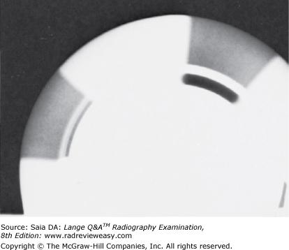
The image in Figure 6–6 was obtained while testing
A rectifier operation in a single-phase x-ray machine.
B rectifier operation in a three-phase x-ray machine.
C timer accuracy in a single-phase x-ray machine.
D timer accuracy in a three-phase x-ray machine.
D timer accuracy in a three-phase x-ray machine.
-A spinning-top test may be performed to evaluate timer accuracy or rectifier efficiency in single-phase equipment. The number of dots or dashes imaged on the IR is counted and should equal the number of radiation “pulses” occurring during that exposure time. Because three-phase equipment does not emit pulsed radiation but rather almost constant potential, a synchronous spinning top must be used to evaluate timer accuracy. The resulting image is a solid black arc. The angle of the arc is measured and should correspond to the known correct angle.
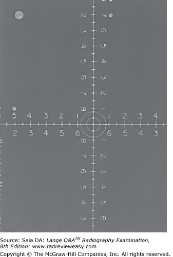
Figure 7–5 illustrates which of the following?
A Screen resolution test
B Nine-penny test
C Collimator accuracy test
D Focal-spot size test
C Collimator accuracy test
-The figure is that of a collimator accuracy test. The collimator is, overall, the most efficient beam-restricting device. It is attached to the tube head, and its upper aperture, the first set of shutters, is placed as close as possible to the x-ray-tube port window. This is done to control the amount of image degrading off-focus radiation leaving the x-ray tube (i.e., radiation produced when electrons strike surfaces other than the focal track). The next set of lead shutters (blades or leaves) actually consists of two pairs of adjustable shutters—one pair for field length and another pair for field width. It is these shutters that the radiographer adjusts when changing the field size and shape. Another important part of the collimator assembly is the light-localization apparatus. It consists of a small light bulb (to illuminate the field) and a mirror. For the light field and x-ray field to correspond accurately, the x-ray-tube focal spot and the light bulb must be exactly at the same distance from the center of the mirror. If the light and x-ray fields do not correspond, IR alignment can be off enough to require a repeat examination. Collimator accuracy should be checked regularly as part of the QA program. NCRP guidelines state that collimators must be accurate to within 2% of the SID. The nine-penny test can also be used to evaluate collimator accuracy, but it has been replaced by the ruled measuring device shown in the figure.
The optimal alignment of the anatomical part being imaged for all digital receptors should be:
A Field centered to IP with at least two collimation margins and parallel to the IP edges
B Centered anywhere on the IP, but having four distinct collimation margins, regardless of parallel orientation to the IP edges
C Centered to the IP with at least one collimation margin aligned to nearest edge of IP
D Field centered to IP with four collimation margins parallel to the IP edges
D Field centered to IP with four collimation margins parallel to the IP edges
-The optimal alignment when using CR is field centered to the plate with four collimation margins parallel to the IP edges (D). Otherwise, the exposure field may not be correctly identified, resulting in a processing error. An exposure field with only two collimation margins and parallel to the IP edges (A) results in extraneous radiation exposure in the top and bottom portions of the receptor. This exposure information may cause misidentification of the exposure field, causing a processing error. Simply exposing an anatomical part anywhere on the receptor (B) has the potential to cause misidentification of the exposure field, causing a processing error. If only one collimation margin is included on the receptor (C), the radiographer has improperly centered the anatomical part. This may result in misidentification of the exposure field and therefore, cause a processing error.
Quality Control (QC) testing is used to evaluate digital display monitors in all of the following ways, except
A Display luminance response
B Display resolution
C Display matrix size
D Display noise
C Display matrix size
-Monitor display luminance response is evaluated on a regular basis using quality control test patterns such as the TG 18-CT and TG 18-LN test patterns (A). Spatial resolution is the quantitative measure of the ability of the digital display monitor to produce separable images of different points of an object with high fidelity. Test patterns such as the TG 18-CX and TG 18-QC test patterns can be used to evaluate this display resolution (B). Image noise is an important factor in determining the visibility of an object. Any high-frequency variations that interfere with detection of the true signal are classified as noise. Digital display monitor noise can be quantified using the TG 18-AFC test pattern, which is based on the method used to determine noticeable luminance differences in the image (D). The display matrix size is calculated by multiplying the number of pixels in a vertical column by the number of pixels in a horizontal row. The matrix size of the monitor display is fixed. No quality control evaluation is necessary to determine variations in this unchanging characteristic (C).
Which of the following possesses the widest dynamic range?
A ALARA
B PBL
C AEC
D CR
D CR
-One of the biggest advantages of CR is the dynamic range, or latitude, it offers. In CR, there is a linear relationship between the exposure given the PSP and its resulting luminescence as it is scanned by the laser. This affords much greater exposure latitude, and technical inaccuracies can be effectively eliminated. Overexposure of up to 500% and underexposure of up to 80% are reported as recoverable, thus eliminating most retakes. This surely affords increased efficiency; however, this does not mean that images can be exposed arbitrarily. The radiographer must keep dose reduction in mind. AEC refers to automatic exposure control and is unrelated to dynamic range or latitude. PBL refers to positive beam limitation and is unrelated to dynamic range or latitude. ALARA is a radiation protection concept referring to keeping occupational dose as low as reasonably achievable.
The image intensifier's input phosphor differs from the output phosphor in that the input phosphor
A is much larger than the output phosphor
B emits electrons, whereas the output phosphor emits light photons
C absorbs electrons, whereas the output phosphor absorbs light photons
D is a fixed size, and the size of the output phosphor can vary
A is much larger than the output phosphor
-The image intensifier's input phosphor is 6 to 9 times larger than the output phosphor. It receives the remnant radiation emerging from the patient and converts it into a fluorescent light image. Very close to the input phosphor, separated only by a thin, transparent layer, is the photocathode. The photocathode is made of a photoemissive alloy, usually a cesium and antimony compound. The fluorescent light image strikes the photocathode and is converted to an electron image, which is focused by the electrostatic lenses to the small output phosphor.
If a high-voltage transformer has 100 primary turns and 50,000 secondary turns and is supplied by 220 V and 100 A, what are the secondary voltage and current?
A 200 A and 110 V
B 200 mA and 110 kVp
C 20 A and 100 V
D 20 mA and 100 kVp
B 200 mA and 110 kVp
-The high-voltage, or step-up, transformer functions to increase voltage to the necessary kilovoltage. It decreases the amperage to milliamperage. The amount of increase or decrease depends on the transformer ratio—the ratio of the number of turns in the primary coil to the number of turns in the secondary coil. The transformer law is as follows: To determine secondary V,
The device used to test the accuracy of the x-ray timer is the
A densitometer
B sensitometer
C penetrometer
D spinning top
D spinning top
-The spinning-top test may be used to test timer accuracy in single-phase equipment. A spinning top is a metal disk with a small hole in its outer edge that is placed on a pedestal about 6 in. high. An exposure is made (e.g., 0.1 s) while the top spins. Because a full-wave-rectified unit produces 120 x-ray photon impulses per second, in 0.1 s the film should record 12 dots (if the timer is accurate). Because three-phase equipment produces almost constant potential rather than pulsed radiation, the standard spinning top cannot be used. An oscilloscope or synchronous spinning top must be employed to test the timers of three-phase equipment.
Which of the following devices converts electrical energy to mechanical energy?
A Motor
B Generator
C Stator
D Rotor
A Motor
-A motor is a device used to convert electrical energy to mechanical energy. The stator and rotor are the two principal parts of an induction motor. A generator converts mechanical energy into electrical energy.
Which of the following statements regarding dual x-ray absorptiometry is (are) true?
- Radiation dose is low.
- Only low-energy photons are used.
- Photon attenuation by bone is calculated.
A 1 only
B 1 and 2 only
C 1 and 3 only
D 1, 2, and 3
C 1 and 3 only
-Dual x-ray absorptiometry (DXA) imaging is used to evaluate bone mineral density (BMD). It is the most widely used method of bone densitometry—it is low-dose, precise, and uncomplicated to use/perform. DXA uses two photon energies—one for soft tissue and one for bone. Since bone is denser and attenuates x-ray photons more readily, photon attenuation is calculated to represent the degree of bone density. Bone densitometry DXA can be used to evaluate bone mineral content of the body, or part of it, to diagnose osteoporosis or to evaluate the effectiveness of treatments for osteoporosis.
In order to avoid background radiation artifacts when using CR, it is important to:
A Erase all image plates that have not been used for 48 hours
B Erase all image plates if there is any question about how long it has been since the plate has been erased
C Erase an image plate if there is any doubt as to when it was last erased, especially in the case of pediatric radiography
D All of these are correct actions
D All of these are correct actions
-It is important to be aware of the necessity of erasing image plates that have not been used for 24 hours. If there is any question about how long it has been since the plate has been through the read/erase cycle, one should erase the plate, especially if pediatric images are being performed. One should also be aware if images suddenly begin to exhibit low contrast, because the erasure system may have failed (D).
Advantages of battery-powered mobile x-ray units include their
- ability to store a large quantity of energy
- ability to store energy for extended periods of time
- lightness and ease of maneuverability
A 1 only
B 1 and 2 only
C 2 and 3 only
D 1, 2, and 3
B 1 and 2 only
-There are two main types of mobile x-ray equipment—capacitor-discharge and battery-powered. Although capacitor-discharge units are light, and therefore fairly easy to maneuver, the battery-powered mobile unit is very heavy (largely because it carries its heavy-duty power source). It is, however, capable of storing a large milliampere-seconds capacity for extended periods of time. These units frequently have a capacity of 10,000 mAs, with 12 hours required for a full charge.
Which of the following is a type of television camera tube that converts a visible image on the output phosphor of the image intensifier into an electronic signal?
A Ionization chamber
B Vidicon
C Charge-coupled device
D Cathode ray tube
B Vidicon
-The Vidicon (B) is a television camera tube used in television fluoroscopy. It is a cylindrical glass vacuum tube that contains a cathode and anode. The cathode (also called the electron gun) is responsible for thermionic emission of electrons, which are accelerated through an electrostatic field that focuses them on a target assembly (anode). The target assembly consists of three layers: the window (thin part of the glass envelope), a metal or graphite signal plate, and a photoconductive layer called the target. When visible light from the output phosphor of the image intensifier tube strikes the anode target assembly, the photoconductive layer of the target conducts electrons. Therefore, in the presence of light, the electrons emitted from the cathode are able to pass through the target to the signal plate and, from there, out of the tube as the video signal. Ionization chambers (A) are found in an automatic exposure control (AEC) system. Air in these chambers is ionized in proportion to the number of X-rays interacting with the air and an electrical signal is generated. This signal, once it reaches a specific magnitude, initiates an exposure timer in the X-ray circuit, which terminates the exposure according to the radiographer’s preselected density setting. A major change from conventional television fluoroscopy to digital fluoroscopy is the use of a charge-coupled device (CCD) (C) in lieu of a television camera tube. The CCD is mounted directly to the output phosphor of the image intensifier tube and is coupled through fiber optics or a lens system to receive the light from the output phosphor. The cathode ray tube (CRT) (D) is a television monitor tube that is viewed by the operator during fluoroscopic evaluation of the anatomy of interest.
The type of x-ray tube designed to turn on and off rapidly, providing multiple short, precise exposures, is
A high speed
B grid-controlled
C diode
D electrode
B grid-controlled
-X-ray tubes are diode tubes; that is, they have two electrodes—a positive electrode called the anode and a negative electrode called the cathode. The cathode filament is heated to incandescence and releases electrons—a process called thermionic emission. During the exposure, these electrons are driven by thousands of volts toward the anode, where they are suddenly decelerated. That deceleration is what produces x-rays. Some x-ray tubes, such as those used in fluoroscopy and in capacitor-discharge mobile units, are required to make short, precise—sometimes multiple—exposures. This need is met by using a grid-controlled tube. A grid-controlled tube uses the molybdenum focusing cup as the switch, permitting very precise control of the tube current (flow of electrons between cathode and anode).
The electron beam in a television cathode ray tube (CRT) is projected onto the output phosphor in a:
A Vertical pattern
B Fixed direct beam
C Broad field
D Raster pattern
D Raster pattern
-The electron beam in a CRT is projected horizontally in a raster pattern (D) on the output phosphor of the CRT, similar to how your eyes move back and forth to read the lines of this text. The electron beam begins in the upper left corner of the phosphor screen and moves to the upper right corner, creating a line of varying intensity of light as it moves. This is called the active trace. The electron beam is then turned off and it returns to the left side of the phosphor screen. This is called the horizontal retrace. A series of active traces, followed by horizontal retraces, until the entire output phosphor screen is scanned, thereby completing a television field. This entire process is repeated to create a second television field to interlace the two fields into one television frame. Thirty of these television frames are produced each second. The electron beam in a CRT is scanned in a horizontal raster pattern (A), from left to right, onto the output phosphor. A fixed direct beam (B) would only covert electrons to light in a specific spot on the output phosphor. A broad electron field (C) would strike a large portion of the output phosphor, preventing the individual lines of varying light intensities to build the anatomical image (C).
If the distance from the focal spot to the center of the collimator's mirror is 6 in., what distance should the illuminator's light bulb be from the center of the mirror?
A 3 in.
B 6 in.
C 9 in.
D 12 in.
B 6 in.
-The collimator assembly includes a series of lead shutters, a mirror, and a light bulb (Figure 5–14). The mirror and light bulb function to project the size, location, and center of the irradiated field. The bulb's emitted beam of light is deflected by a mirror placed at an angle of 45 degrees in the path of the light beam. In order for the projected light beam to be the same size as the x-ray beam, the focal spot and the light bulb must be exactly the same distance from the center of the mirror.
What is the device that directs the light emitted from the image intensifier to various viewing and imaging apparatus?
A Output phosphor
B Beam splitter
C Spot-film changer
D Automatic brightness control
B Beam splitter
-The light image emitted from the output phosphor of the image intensifier is directed to the TV monitor for viewing and sometimes to recording devices such as a spot-film camera or cine film. The light is directed to these places by a beam splitter or objective lens located between the output phosphor and the TV camera tube (or CCD). The majority of the light will go to the recording device, whereas a small portion goes to the TV so that the procedure may continue to be monitored during filming.
Off-focus, or extrafocal, radiation is minimized by
A avoiding the use of very high kilovoltages
B restricting the x-ray beam as close to its source as possible
C using compression devices to reduce tissue thickness
D avoiding extreme collimation
B restricting the x-ray beam as close to its source as possible
-Off-focus, or extrafocal, radiation is produced as electrons strike metal surfaces other than the focal track and produce x-rays that emerge with the primary beam at a variety of angles. This radiation is responsible for indistinct images outside the collimated field. Mounting a pair of shutters as close to the source as possible minimizes off-focus radiation.
Digital fluoroscopy units use which of the following devices in lieu of a television camera tube?
A charge-coupled device (CCD)
B photometer
C photomultiplier tube
D light gate
A chargIn a digital fluoroscopy unit, a charge-coupled device (CCD) (A) is mounted on the output phosphor of the image intensifier tube and is coupled via fiber optics or a lens system. The sensitive layer of crystalline silicon within the CCD responds to the light from the output phosphor, creating an electrical charge. The charges are sampled, pixel by pixel, and then manipulated to produce a digital image. A photometer(B) is used to measure luminance response and uniformity of monitors used in digital imaging. Two types are commonly used: near-range and telescopic. Near-range photometers are used for measuring a monitor’s luminance at close range, whereas telescopic photometers measure this from a distance of one meter. Background ambient light should be kept constant when either photometer is used. A photomultiplier tube (C) receives light energy from the scanned IP in a CR reader and converts it into an electrical (analog) signal that can then be converted to a binary signal in the analog-to-digital convertor (ADC). This binary signal is then processed by a computer to develop a diagnostic image. Newer CR readers may use a charged-coupled device (CDC) to convert the light energy in to an electrical signal. The light gate (or channeling guide) (D) in a CR reader channels the light energy released by the image plate as it is scanned by the laser beam to the photomultiplier tube (D).e-coupled device (CCD)
-
When using the smaller field in a dual-field image intensifier,
1.a smaller patient area is viewed.
2.the image is magnified.
3.the image is less bright.
A 1 only
B 1 and 3 only
C 2 and 3 only
D 1, 2, and 3
D 1, 2, and 3
-When a dual-field image intensifier is switched to the smaller field, the electrostatic focusing lenses are given a greater charge to focus the electron image more tightly. The focal point, then, moves further from the output phosphor (the diameter of the electron image is therefore smaller as it reaches the output phosphor), and the brightness gain is somewhat diminished. Hence, the patient area viewed is somewhat smaller and is magnified. However, the minification gain has been reduced and the image is somewhat less bright.
In fluoroscopy, the automatic brightness control is used to adjust the
A kVp and mA
B backup timer
C milliamperage (mA) and time
D kilovoltage (kV) and time
A kVp and mA
-As body areas of different thicknesses and densities are scanned with the image intensifier, image brightness and contrast require adjustment. The ABC functions to maintain constant brightness and contrast of the output screen image, correcting for fluctuations in x-ray beam attenuation with adjustments in kilovoltage and/or milliamperage. There are also brightness and contrast controls on the monitor that the radiographer can regulate.
The batteries in battery-operated mobile x-ray units provide power to
- the x-ray tube
- machine locomotion
- the braking mechanism
A 1 only
B 2 only
C 1 and 2 only
D 1, 2, and 3
D 1, 2, and 3
-Mobile x-ray machines are smaller and more compact than their fixed counterparts in the radiology department. It is important that they be relatively easy to move, that their size allows entry into patient rooms, and that their locks enable securing of the x-ray tube into the required positions. Mobile x-ray machines are cordless and are either the battery-operated type or the condenser-discharge type. The battery-operated type is probably the most commonly used where consistent and high-energy output is required. Two sets of batteries are used in these mobile units: One set is used for operating the motor that drives the unit and operates the braking mechanism (“dead man” brake), and the other set is used for operating the x-ray tube. Periodic recharging of the batteries is required.
Which part of an induction motor is located outside the x-ray tube glass envelope?
A Filament
B Focusing cup
C Stator
D Rotor
C Stator
-The anode is made to rotate through the use of an induction motor. An induction motor has two main parts, a stator and a rotor. The stator is the part located outside the glass envelope and consists of a series of electromagnets occupying positions around the stem of the anode. The stator's electromagnets are supplied with current and the associated magnetic fields function to exert a drag or pull on the rotor within the glass envelope. The anode is a 2- to 5-in. diameter molybdenum or graphite disc with a beveled edge. The beveled surface has a focal track of tungsten and rhenium alloy. The anode rotates at about 3,600 rpm (high-speed anode rotation is about 10,000 rpm), so that heat generated during x-ray production is evenly distributed over the entire track. Rotating anodes can withstand delivery of a greater amount of heat for a longer period of time than stationary anodes.
What x-ray tube component does the number 6 in Figure 5–4 indicate?
A Anode stem
B Rotor
C Stator
D Focal track
C Stator
-The figure illustrates the component parts of a rotating-anode x-ray tube enclosed within a glass envelope (number 3) to preserve the vacuum necessary for x-ray production. Number 4 is the rotating anode with its beveled focal track at the periphery (number 8) and its stem (at number 5). Numbers 6 and 7 are the stator and rotor, respectively—the two components of an induction motor—whose function it is to rotate the anode. Number 1 is the filament of the cathode assembly, which is made of thoriated tungsten and functions to liberate electrons (thermionic emission) when heated to white hot (incandescence). Number 2 is the molybdenum focusing cup, which functions to direct the liberated filament electrons to the focal spot.
The advantages of capacitor-discharge mobile x-ray equipment include
- compact size
- light weight
- high kilovoltage capability
A 1 only
B 1 and 2 only
C 2 and 3 only
D 1, 2, and 3
B 1 and 2 only
-Mobile x-ray machines are compact and cordless and are either the battery-operated type or the condenser-discharge type. Condenser-discharge mobile x-ray units do not use batteries; this type of mobile unit requires that it be charged before each exposure. A condenser (or capacitor) is a device that stores electrical energy. The stored energy is used to operate the x-ray tube only. Because this machine does not carry many batteries, it is much lighter and does not need a motor to drive or brake it. The major disadvantage of the capacitor/condenser-discharge unit is that as the capacitor discharges its electrical charge the kilovoltage gradually decreases throughout the length of the exposure—therefore limiting tube output and requiring recharging between exposures.
Inadequate collimation in CR imaging can result in an image that is too
- light
- dark
- noisy
A 1 only
B 1 and 2 only
C 2 and 3 only
D 1, 2, and 3
D 1, 2, and 3
-It is important to note that histogram appearance as well as patient dose can be affected by the radiographer's knowledge and skill using digital imaging, in addition to his or her degree of accuracy in positioning and centering. Collimation is exceedingly important to avoid histogram analysis errors. Lack of adequate collimation can result in signals outside the anatomical area being included in the exposure data recognition/histogram analysis. This can result in a variety of histogram analysis errors, including excessively light, dark, or noisy images.
The output phosphor can be coupled with the Vidicon TV camera or charge-coupled device (CCD) via
- fiber optics.
- an image distributor or lens.
- closed-circuit TV.
A 1 only
B 1 and 2 only
C 2 and 3 only
D 1, 2, and 3
B 1 and 2 only
-The output phosphor of the image intensifier displays the brighter, minified, and inverted image. From the output phosphor, the light image is conveyed to its destination by some kind of image distributor—either a series of lenses and a mirror or via fiber optics. Fiber optics is often the method of choice where equipment size is of concern (e.g., mobile equipment). The image distributor, that is, the lens or fiber optics, then sends the majority of light to the TV monitor for direct viewing and the remaining light (about 10%) to the IR (e.g., photospot camera).
The primary parts of the cathode include the
1. focal track.
2. filament.
3. focusing cup.
A 1 only
B 1 and 2 only
C 2 and 3 only
D 1, 2, and 3
C 2 and 3 only
-The typical diode x-ray tube consists of a positive electrode (the anode) and a negative electrode (the cathode). Electrons are released from the cathode's filament, directed toward the anode by the cathode's focusing cup, and delivered at very high speed to the anode's focal track.
Which of the following may occur if the X-ray exposure field is not properly collimated, positioned, and sized?
A Modulation transfer function failure
B Moiré artifact
C Exposure field recognition errors may occur
D Ghost artifact
C Exposure field recognition errors may occur
-If the X-ray exposure field is improperly collimated, positioned, and sized, exposure field recognition errors can occur (C). These can lead to histogram analysis errors due to signals generated from outside of the exposure field. This may result in dark, light, or noisy images. The MTF, or modulation transfer function (A) is a mathematical function that measures the ability of a digital detector to transfer its spatial resolution characteristics of the image.
If a radiographic grid has a frequency that approximates the CR scan frequency and the grid strips are oriented in the same direction as the scan, the Moiré artifact may be observed (B). The appearance of ghost artifacts can be seen when CR image plates are incompletely erased. If an image plate has not been used for 24 hours, it should be erased again before using it for a diagnostic radiographic exposure (A).
Europium-activated barium fluorohalide is associated with
A fluoroscopy
B image intensifiers
C PSP storage plates
D filament material
C PSP storage plates
-Image Plates (IPs) have a protective function (for the PSP/storage plate within) and can be used in the Bucky tray or directly under the anatomic part; they need not be light-tight because the PSP is not light sensitive. The IP has a thin lead-foil backing (similar to traditional cassettes) to absorb backscatter. Inside the IP is the photostimulable phosphor (PSP) storage plate. This PSP storage plate within the IP has a layer of europium-activated barium fluorohalide that serves as the IR as it is exposed in the traditional manner and receives the latent image. The PSP can store the latent image for several hours;after about 8 hours, noticeable image fading will occur.
One reason why only one image is preferred per image plate is:
A To ensure that the anatomical part is properly centered to avoid undercutting of the image
B To allow the radiologist to split the PACS monitor and display the current image and a prior image side-by-side for comparison
C To ensure optimal radiation safety, since only one image is exposed on one image plate
D To reduce the chances of grid cutoff artifacts
B To allow the radiologist to split the PACS monitor and display the current image and a prior image side-by-side for comparison
-Exposing only one image on one image plate does not ensure proper centering (A). This is a technical skill required of the radiographer to ensure the anatomical part is properly centered. One reason to collect only one image per IP (B) is the ability of the radiologist to then split the PACS monitor and display the current image and the prior image side by side for comparison. Radiation safety is not optimized by exposing one image on one imaging plate. The required number of projections (exposures) is required, regardless (C). Grid cutoff artifacts can occur with faulty tube/image receptor alignment or improper SID for any radiographic exposure, regardless of the number of projections taken on an image plate (D).
Backscatter on a digital image can cause an artifact called a
A Phantom image artifact
B Moiré artifact
C Static artifact
D Grid cutoff artifact
A Phantom image artifact
-The appearance of phantom image artifact (A) can be seen when excessive backscatter exposes the image receptor. The back side of the image receptor should be shielded with lead to reduce exposure to backscatter radiation. If a radiographic grid has a frequency that approximates the CR scan frequency and the grid strips are oriented in the same direction as the scan, the Moiré artifact may be observed (B). Grid cutoff artifacts are seen as a decrease in receptor exposure on one side of the image when the central ray is off-centered or not perpendicular to either a non-focused or focused grid, or onboth sides when the central ray is properly centered but the focal range is exceeded (caused by improper SID) when using a focused grid (D). Static artifacts may be seen on radiographic film imaging
Which of the following is (are) tested as part of a quality control (QC) program?
- Beam alignment
- Reproducibility
- Linearity
A 1 only
B 1 and 2 only
C 1 and 3 only
D 1, 2, and 3
D 1, 2, and 3
-Each of the three is included in a good QC program. Beam alignment must be accurate to within 2% of the SID. Reproducibility means that repeated exposures at a given technique must provide consistent intensity. Linearity means that a given milliampere-second setting, using different milliampere stations with appropriate exposure-time adjustments, will provide consistent intensity.
Although the stated focal-spot size is measured directly under the actual focal spot, focal-spot size in fact varies along the length of the x-ray beam. At which portion of the x-ray beam is the effective focal spot the largest?
A At its outer edge
B Along the path of the CR
C At the cathode end
D At the anode end
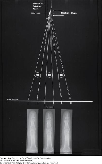
C At the cathode end
-X-ray tube targets are constructed according to the line-focus principle—the focal spot is angled (usually 12–17 degrees) to the vertical. As the actual focal spot is projected downward, it is foreshortened; thus, the effective focal spot is smaller than the actual focal spot. As the focal spot is projected toward the cathode end of the x-ray beam, it becomes larger and approaches its actual size. Figure 7–22 illustrates the variation of the effective focal-spot size along the longitudinal tube axis. As the effective focal spot becomes larger toward the cathode end, the images of the phalanges illustrate gradual loss of spatial resolution
Which of the following digital post-processing methods remove high-frequency noise from the image?
A Edge enhancement
B Windowing
C Smoothing
D Aliasing
C Smoothing
-Image smoothing (C) is a type of spatial frequency filtering performed during digital image post-processing. Also known as low-pass filtering, smoothing can be achieved by averaging each pixel’s frequency with surrounding pixel values to remove high-frequency noise. The result is reduction in noise and contrast. Smoothing (low-pass filtering) is useful for viewing small structures such as fine bone tissues. Edge enhancement (A) is a type of post-processing image manipulation, which can be effective for enhancing fractures and small, high-contrast tissues. In digital imaging, after the signal is obtained for each pixel, the signals are averaged to shorten processing time and decrease storage needs. The larger the number of pixels involved in the averaging, the smoother the image appears. The signal strength of one pixel is averaged with the strength of its neighboring pixels. Edge enhancement is achieved when fewer neighboring pixels are included in the signal average. Therefore, the smaller the number of neighboring pixels, the greater the edge enhancement. Windowing (B) is a post-processing method of adjusting the brightness and contrast in the digital image. There are two types of windowing: level and width. Window level adjusts the overall image brightness. When the window level is increased, the image becomes darker. When decreased, the image becomes brighter. Window width adjusts the ratio of white to black, thereby changing image contrast. Narrow window width provides higher contrast (short-scale contrast), whereas wide window width will produce an image with less contrast (long-scale contrast). Aliasing (D) is an image artifact that occurs when the spatial frequency is greater than the Nyquist frequency and the sampling occurs less than twice per cycle. This causes loss of information and a fluctuating signal and wrap-around image is produced, which appears as two superimposed images that are slightly out of alignment, resulting in a moiré effect. The Nyquist theorem states that when sampling a signal (such as the conversion from the analog to digital image), the sampling frequency must be greater than twice the bandwidth of the input signal so that reconstruction of the original image properly displays the anatomy of interest.

In the radiographic rating charts shown below, what is the maximum safe kVp that may be used with the 1-mm focal spot, single-phase x-ray tube, using 300 mA and 1/50-second exposure?
A 80
B 95
C 105
D 112
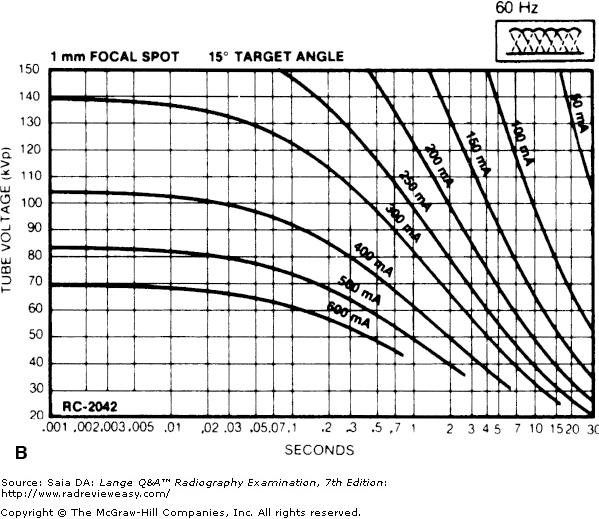
C 105
-A radiographic rating chart enables the radiographer to determine the maximum safe mA, exposure time, and kVp for a given exposure using a particular x-ray tube. Because the heat load that an anode will safely accept varies with the size of the focal spot, type of rectification, and anode rotation, these variables must also be identified. Each x-ray tube has its own characteristics and its own rating chart. First, find the chart with the identifying single-phase sine wave in the upper right corner of the chart and the correct focal spot size in the upper left corner of the chart (chart C). Once the correct chart has been identified, locate 1/50 (0.02) second on the horizontal axis and follow its line up to where it intersects with the 300-mA curve. Then draw a line to where this point meets the vertical (kVp) axis; it meets at between 100 and 110 kVp, or approximately 107 kVp. This is the maximum permissible kVp exposure at the given mAs for this x-ray tube. The radiographer should always use somewhat less than the maximum exposure. This same procedure is followed to answer the next two questions.
If 85 kV and 20 mAs were used for a particular abdominal exposure with single-phase equipment, what mAs would be required to produce a similar radiograph with 3-phase, 12-pulse equipment.
A 40
B 25
C 20
D 10
D 10
-Single-phase radiographic equipment is much less efficient than three-phase equipment because it has a 100% voltage ripple. With three-phase equipment, voltage never drops to zero, and x-ray intensity is significantly greater. To produce similar receptor exposure, only two thirds of the original mAs would be used for three-phase, six-pulse equipment (2/3 × 20 = 13 mAs). With 3-phase, 12-pulse equipment, the original mAs would be cut in half; thus, 10 mAs should be used.
The smallest digital detectors (approximately 100 microns) provide the best spatial resolution and, therefore, are best-suited for use in:
A Fluoroscopy procedures
B Mammography
C Pediatric radiography
D Long bone measurement to ensure measurement accuracy
B Mammography
-Although spatial resolution is important in all radiographic or fluoroscopic applications, the systems affording the maximum spatial resolution are applied to those examinations such as mammography (B) where microscopic lesions must be detected. Lesions typically detected in fluoroscopic images (A) are at the macroscopic level. Maximum spatial resolution in cassetteless digital systems is limited by the size of the digital detectors. In the case of mammography, the best possible spatial resolution is required to ensure the detection and display of micro-calcifications, which may be suggestive of malignant lesions (B). Spatial resolution is important in pediatric imaging (C) and those systems used for this application provide sufficient resolution to display diagnostically acceptable images. The spatial resolution is not as important for long-bone measurement (D) as it is in mammography. These radiographic procedures, regardless of the spatial resolution, are intended to provide measurements from one joint to another, which does not require optimal spatial resolution.
A device contained within many CR readers that functions to convert light energy released by the PSP into electrical energy, is called a:
A Transilluminator
B Photomultiplier tube
C Light gate
D Penetrometer
B Photomultiplier tube
-A photomultiplier tube (B) receives light energy from the scanned PSP plate in a CR reader and converts it into an electrical (analog) signal that can then be converted to a binary signal in the analog-to-digital convertor (ADC). This binary signal is then processed by a computer to develop a diagnostic image. Newer CR readers may use a charged-coupled device (CDC) to convert the light energy into an electrical signal. The light gate (C), (or channeling guide,) in a CR reader channels the light energy released by the image plate as it is scanned by the laser beam to the photomultiplier tube. A penetrometer (D) (or aluminum step wedge) is a device used for quality control testing in film radiography. After an exposure of this device is made while it rests on top of a film cassette, the film within the cassette is chemically processed. The resultant image demonstrates multiple steps of densities. The densities can be measured by a densitometer to determine the film contrast index and other processing-related factors. A sensitometer, which is an electrical device, can be used in lieu of the penetrometer and projects a preset light exposure on the film in the darkroom. After the film is processed, multiple steps of densities, similar to those achieved using the penetrometer, are demonstrated and can then be measured by a densitometer in the same fashion. A transilluminator is a device used for imaging of fluorescent DNA and proteins in a molecular biology lab (A).
Sampling frequency in computed radiography (CR) is expressed as:
A The TFT array size
B An inverse relationship between focal spot size and matrix size
C The light spread between the image plate and the light guide of the scanner
D Pixels/mm or pixel density
D Pixels/mm or pixel density
-The TFT array is found in direct and indirect digital detector systems, not in computed radiography (CR) (A). The focal spot size (B) influences image resolution but has no influence on the number of pixels per millimeter that determines the sampling frequency. The light spread between the image plate and the light guide of the scanner (C) refers to computed radiography (CR) systems, not direct or indirect digital detector systems. Sampling frequency, also referred to as pixel density (pixels/mm), is expressed as pixels per millimeter. The sampling frequency determines the pixel pitch, which, in turn, determines the spatial resolution (D).
“Saturation” of an image in CR means that:
A The CR reader has difficulty converting insufficient exposure signals to produce a diagnostic image; all electronic enhancement mechanisms are maximized
B Beyond a certain exposure level, a large number of pixels will be at maximum digital value (black), resulting in loss of visibility of anatomical structures in that region.
C There is a large amount of scatter radiation that is contributing to loss of anatomical image detail due to loss of contrast, thus decreasing diagnostic quality of the image
D The CR image reader has adequately, and completely, read all the exposure intensities from the pixels resulting from the exposure
B Beyond a certain exposure level, a large number of pixels will be at maximum digital value (black), resulting in loss of visibility of anatomical structures in that region.
-“Saturation” of the CR image plate refers to overexposure of the image plate, not underexposure (A). “Saturation” means that, beyond a certain exposure level, a large number of the pixels will be at the maximum digital value, i.e., black (B). Therefore, there is no signal difference in the very high exposure areas, resulting in a loss of anatomical structures visualized in that region. It is therefore important for radiographers to use the appropriate exposure level for any particular anatomical part and not rely on the CR reader to adjust for overexposure. This is also critical to ensure proper adherence to the ALARA principle and to honor professional ethics. Although scatter radiation contributes to the exposure of the image plate (C), it is mainly the excessive exposure setting that “saturates” the pixels and prevents the CR reader from displaying densities darker than the blackest areas. The “saturation” exposure prevents the CR reader from reading exposure intensities beyond the blackest densities in the pixels (D).
To maintain image clarity in an image-intensifier system, the path of electron flow from the photocathode to the output phosphor is controlled by
A the accelerating anode
B electrostatic lenses
C the vacuum glass envelope
D the input phosphor
B electrostatic lenses
-The input phosphor of an image intensifier receives remnant radiation emerging from the patient and converts it to a fluorescent light image. Directly adjacent to the input phosphor is the photocathode, which is made of a photoemissive alloy (usually a cesium and antimony compound). The fluorescent light image strikes the photocathode and is converted to an electron image. The electrons are carefully focused to maintain image resolution by the electrostatic focusing lenses through the accelerating anode and to the output phosphor for conversion back to light.
The total brightness gain of an image intensifier is the product of
- flux gain
- minification gain
- focusing gain
A 1 only
B 2 only
C 1 and 2 only
D 1 and 3 only
C 1 and 2 only
-The brightness gain of image intensifiers is 5,000 to 20,000. This increase is accounted for in two ways. As the electron image is focused to the output phosphor, it is accelerated by high voltage (about 25 kV). The output phosphor is only a fraction of the size of the input phosphor, and this decrease in image size represents brightness gain, termed minification gain. The ratio of the number of x-ray photons at the input phosphor compared to the number light photons at the output phosphor is termed flux gain.Total brightness gain is equal to the product of minification gain and flux gain.
All of the following are equipment options that may be used to record the anatomical image in mobile radiography, except:
A Tethered flat panel
B Remote (wireless) digital flat panel array
C Scanned projection radiography (SPR)
D Conventional radiographic film
C Scanned projection radiography (SPR)
-In scanned projection radiography (SPR) (A), typically of the chest, the X-ray beam is collimated to a thin fan by pre-patient collimators. Post-patient image-forming X-rays likewise are collimated to a thin fan that corresponds to a detector array consisting of a scintillation phosphor, usually NaI or CsI, which is married to a linear array of CCDs through a fiberoptic path. This type of unit is a fixed unit located in the radiology department. Answers A, B and D can be used with mobile radiographic units to record the anatomical image.
Which of the following will occur as a result of a decrease in the anode target angle?
1.Less pronounced anode heel effect
2.Decreased effective focal spot size
3.Greater photon intensity toward the cathode side of the x-ray tube
A 1 only
B 1 and 2 only
C 2 and 3 only
D 1, 2, and 3
C 2 and 3 only
-Target angle has a pronounced geometric effect on the effective, or projected, focal spot size. As the target angle decreases, the effective (projected) focal spot becomes smaller. This is advantageous because it will improve spatial resolution without creating a heat-loading crisis at the anode (as would occur if the actual focal spot size were reduced to produce a similar resolution improvement). There are disadvantages, however. With a smaller target angle, the anode heel effect increases; photons are more noticeably absorbed by the "heel" of the anode, resulting in a smaller percentage of x-ray photons at the anode end of the x-ray beam and a concentration of x-ray photons at the cathode end of the radiograph