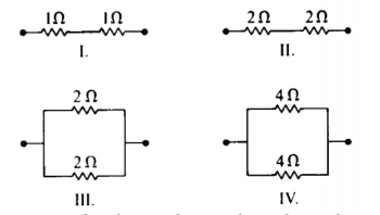
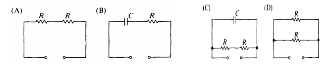
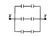
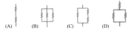
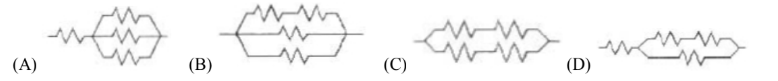
Multiple Correct. Which arrangements of resistors shown above have
the same resistance between the terminals? Select two answers
(A)
I
(B) II
(C) III
(D) IV
A, D
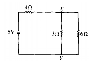
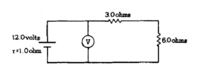
In the circuit shown above, what is the value of the potential
difference between points X and Y if the 6–volt
battery has no
internal resistance?
(A) 2 V (B) 3 V (C) 4 V (D) 6V
(A)
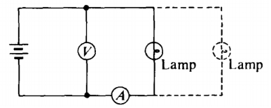
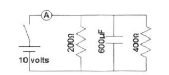
How would the ammeter reading change when another lamp is connected
in parallel with the first lamp as shown by the dashed lines?
(A)
increases, because the current through the ammeter splits to feed both
branches
(B) remains the same, because the ammeter measures the
current provided by the battery
(C) decreases, because the
resistance of the circuit is increased
(D) remains the same,
because energy is conserved in the circuit
(A)
How would the voltmeter reading change when another lamp is connected
in parallel with the first lamp as shown by the dashed lines?
(A)
decreases, because the current is split between the two
branches
(B) remains the same, because charge is conserved in the
circuit
(C) increases, because the resistance of the circuit is
increased
(D) remains the same, because energy is conserved in
the circuit
(D)
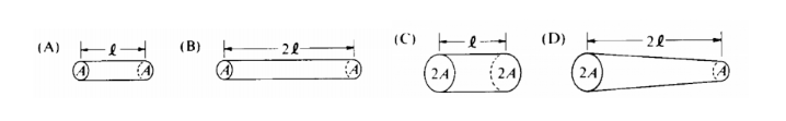
The four resistors shown below have the lengths and cross–sectional
areas indicated and are made of material
with the same
resistivity. Which has the greatest resistance?
(A)
(B)
(C)
(D)
(B)
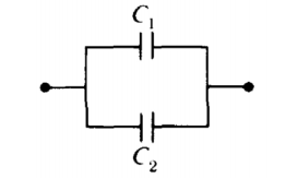
Two capacitors are connected in parallel as shown above. A voltage V
is applied to the pair. What is the ratio of charge stored on C1 to
the charge stored on C2, when C1 = 1.5C2 ?
(A) 2/3
(B) 1
(C) 3/2
(D) 9/4
(C)
The five incomplete circuits below are composed of resistors R, all
of equal resistance, and capacitors C, all of
equal capacitance.
A battery that can be used to complete any of the circuits is available.
Into which circuit should the battery be connected to obtain the
greatest steady power dissipation?
(A) A
(B) B
(C) C
(D) D
(D)
The five incomplete circuits below are composed of resistors R, all
of equal resistance, and capacitors C, all of
equal capacitance.
A battery that can be used to complete any of the circuits is available.
Which circuit will retain stored energy if the battery is connected to it and then disconnected?
(A) A
(B) B
(C) C
(D) D
(B)
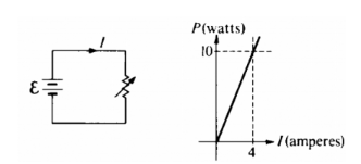
The circuit shown above left is made up of a variable resistor and a
battery with negligible internal resistance. A graph of the power P
dissipated in the resistor as a function of the current I supplied by
the battery is given above right. What is the emf of the
battery?
(A) 0.025 V
(B) 2.5 V
(C) 6.25 V
(D)
40 V
(B)
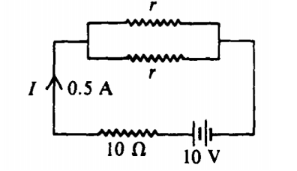
In the circuit shown above, the value of r for which the current I is
0.5 ampere is
(A) 1 ꭥ
(B) 5 ꭥ
(C) 10 ꭥ
(D) 20 ꭥ
(D)
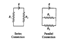
In the diagrams above, resistors R1 and R2 are shown in two different
connections to the same source of emf E that has no internal
resistance. How does the power dissipated by the resistors in these
two cases compare?
(A) It is greater for the series connection,
because the current is not split.
(B) It is greater for the
series connection, because the equivalent resistance is
greater
(C) It is greater for the parallel connection, because
the total current is greater.
(D) It is greater for the parallel
connection, because both resistors have the same voltage.
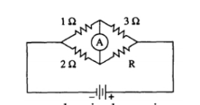
(C)
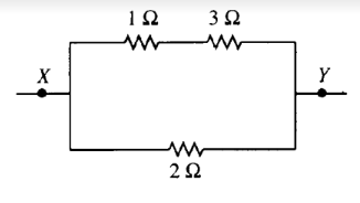
The diagram above shows part of a closed electrical circuit. When
there is a steady current in the circuit, the amount of charge passing
a point per unit of time is
(A) greater in the 1 ꭥ resistor than
in the 3 ꭥ resistor
(B) greater in the 1 ꭥ resistor than in the 2
ꭥ resistor
(C) greater in the 2 ꭥ resistor than in the 3 ꭥ
resistor
(D) greater at point X than at point Y
(C)
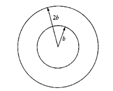
Two concentric circular loops of radii b and 2b, made of the same
type of wire, lie in the plane of the page, as shown above. The total
resistance of the wire loop of radius b is R. What is the resistance
of the wire loop of radius 2b?
(A) R/2
(B) R
(C) 2R
(D) 4R
(C)
The total capacitance of several capacitors in parallel is the sum of
the individual capacitances for which of the following
reasons?
(A) The charge on each capacitor depends on its
capacitance, but the potential difference across each is the
same.
(B) The charge is the same on each capacitor, but the
potential difference across each capacitor depends on
its
capacitance.
(C) Capacitors in a circuit always combine
like resistors in series.
(D) The parallel combination increases
the effective separation of the plates.
(A)
A wire of length L and radius r has a resistance R. What is the
resistance of a second wire made from the same material that has a
length L/2 and a radius r/2?
(A) 4R
(B) 2R
(C) R
(D) R/2
(B)
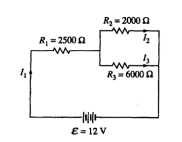
Which current is greater I1 or I2?
(A) I1 is greater, because it
has more resistance.
(B) I2 is greater, because it has less
resistance.
(C) I1 is greater, because of charge
conservation.
(D) I2 is greater, because of energy conservation.
(C)
What is the current I1?
(A) 1 mA
(B) 3 mA
(C) 4 mA
(D) 12 mA
(B)
Which of the following changes would increase the value of
I1?
(A) Remove R3 and the branch containing it.
(B) Replace
R2 with another 6000 Ohm resistor.
(C) Add an 8000 Ohm resistor
in parallel with R2 and R3.
(C)
A 60-W incandescent bulb and a 13.3-Watt compact fluorescent light
are both plugged into a 110-volt household circuit and lit. Which bulb
has the greater resistance?
(A) Neither, since they are connected
across the same potential difference.
(B) The 60-W bulb, because
it draws more current.
(C) The 13.3-W bulb, because it uses less
power
(D) The 13.3-W bulb, because it is more efficient.
(B)
In the circuit shown above, what is the resistance R?
(A) 3
ꭥ
(B) 4 ꭥ
(C) 6 ꭥ
(D) 12 ꭥ
(B)
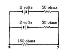
In the circuit shown above, the current in each battery is 0.04
ampere. What is the potential difference between the points x and
y?
(A) 8 V
(B) 2 V
(C) 0 V
(D) 4 V
(C)
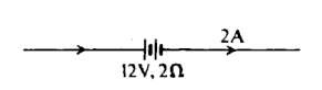
A 12–volt storage battery, with an internal resistance of 2, is
being charged by a current of 2 amperes as shown in the diagram above.
Under these circumstances, a voltmeter connected across the terminals
of the battery will read
(A) 8 V
(B) 10 V
(C) 12 V
(D) 16 V
(D)
The batteries in each of the circuits shown above are identical and
the wires have negligible resistance.
In which circuit is
the current furnished by the battery the greatest?
(A) A
(B) B
(C) C
(D) D
(A0
The batteries in each of the circuits shown above are identical and
the wires have negligible resistance.
In which circuit is
the equivalent resistance connected to the battery the
greatest?
(A) A
(B) B
(C) C
(D) D
(C)
The batteries in each of the circuits shown above are identical and
the wires have negligible resistance.
Which circuit
dissipates the least power?
(A) A
(B) B
(C) C
(D) D
(C)
When two identical parallel–plate capacitors are connected in series,
which of the following is true of the equivalent capacitance?
(A)
It depends on the charge on each capacitor.
(B) It depends on the
potential difference across both capacitors.
(C) It is larger
than the capacitance of each capacitor.
(D) It is smaller than
the capacitance of each capacitor.
(C)
The emf of a battery is 12 volts. When the battery delivers a steady
current of 0.5 ampere to a load, the potential difference between the
terminals of the battery is 10 volts. What terminal voltage would you
expect if the battery were connected to a load with less
resistance?
(A) 12 V
(B) 10 V
(C) Between 10 and 12 V
(D) Less than 10 V
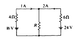
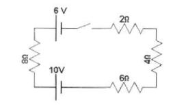
(D)
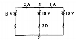
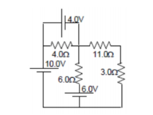
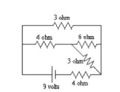
In the circuit shown above, the emf's of the batteries are given, as
well as the currents in the outside branches and the resistance in the
middle branch. What is the magnitude of the potential difference
between X and Y?
(A) 4 V
(B) 8 V
(C) 10 V
(D)
12 V
(D)
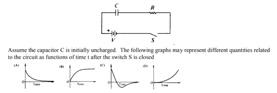
Which graph best represents the voltage versus time across the
resistor R?
(A) A
(B) B
(C) C
(D) D
(A)
Which graph best represents the current versus time in the
circuit?
(A) A
(B) B
(C) C
(D) D
(A)
Which graph best represents the voltage across the capacitor versus
time?
(A) A
(B) B
(C) C
(D) D
(B)
A wire of resistance R dissipates power P when a current I passes
through it. The wire is replaced by another wire with resistance 3R.
The power dissipated by the new wire when the same current passes
through it is
(A) P/9
(B) P/3
(C) P
(D) 3P
(D)
The diagram above represents a circuit of six 2–microfarad
capacitors. What potential difference must be applied between points X
and Y so that the charge on each plate of each capacitor will have
magnitude 6
microcoulombs?
(A) 3V
(B) 6 V
(C) 9
V
(D) 18 V
(B)
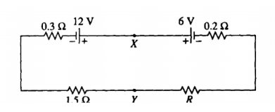
In the circuit above, the emf's and the resistances have the values
shown (0.3 Ω, 0.2 Ω and 1,5 Ω) . The current I in
the circuit is
2 amperes.
34. The resistance R is
(A) 1 ꭥ
(B) 2
ꭥ
(C) 3 ꭥ
(D) 4 ꭥ
(A)
In the circuit above, the emf's and the resistances have the values
shown (0.3 Ω, 0.2 Ω and 1,5 Ω) . The current I in
the circuit is
2 amperes.
The potential difference between points X and Y
is
(A) 1.2 V
(B) 6.0 V
(C) 8.4 V
(D) 10.8 V
(C)
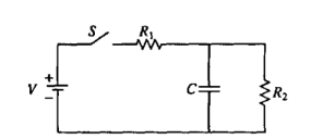
In the circuit shown above, the battery supplies a constant voltage V
when the switch S is closed. The value of the capacitance is C, and
the value of the resistances are R1 and R2. In the time after the
switch is closed, the current supplied by the battery is
(A)
constant, because batteries always provide constant current
(B)
constant, because the capacitor is a open circuit and doesn’t affect
the two resistors in series
(C) decreasing, because current
initially flows to the capacitor
(D) decreasing, because it
becomes zero when the capacitor is full
(C)
If the ammeter in the circuit above reads zero, what is the
resistance R ?
(A) 1.5 ꭥ
(B) 2 ꭥ
(C) 4 ꭥ
(D) 6 ꭥ
(D)
If the current through the ammeter is to flow toward the bottom of
the page, how must the resistance R compare to the value found in
#37?
(A) it must be larger, so that the voltage across R
increases
(B) it must be larger, so that the equivalent
resistance of the circuit increases
(C) it must be smaller, so
that the voltage across R decreases
(D) it must be smaller, so
that the equivalent resistance of the circuit decreases
(A)
A resistor R and a capacitor C are connected in series to a battery
of terminal voltage V0. Which of the following equations relating the
current I in the circuit and the charge Q on the capacitor describes
this circuit?
(A) V0 + QC – I2R = 0
(B) V0 – Q/C – IR = 0
(C) V0
2 – Q2/2C – I2R = 0
(D) V0
– CI – I2R = 0
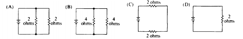
(B)
Which of the following combinations of 4 resistors would dissipate 24 W when connected to a 12 Volt battery?
(A)
(B)
(C)
(D)
(D)
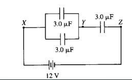
Three identical capacitors, each of capacitance 3.0 F, are connected
in a circuit with a 12 V battery as shown above. The potential
difference between points Y and Z is
(A) 6 V, because all
capacitors will have the same potential difference
(B) 8 V,
because charge is conserved in the set of wires containing point
Y.
(C) 6 V, because charge is conserved in the set of wires
containing point Y.
(D) 8 V, because all capacitors have the same charge.
(B)
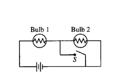
The circuit in the figure above contains two identical lightbulbs in
series with a battery. At first both bulbs glow with equal brightness.
When switch S is closed, which of the following occurs to the
bulbs?
Bulb
I Bulb 2
(A) Goes out Gets brighter
(B) Gets brighter Goes
out
(C) Gets brighter Gets slightly dimmer
(D) Gets slightly
dimmer Gets brighter
(B)
When the switch S is open in the circuit shown above, the reading on
the ammeter A is 2.0 A. When the switch is closed, the reading on the
ammeter is
(A) doubled
(B) increased slightly but not
doubled
(C) the same
(D) decreased slightly
(B)
Two conducting cylindrical wires are made out of the same material.
Wire X has twice as much resistance than wire Y. Which of the
following could be true?
(A) Wire X is twice the diameter of wire
Y.
(B) Wire X is twice as long and twice the diameter of wire
Y.
(C) Wire Y is twice as long and twice the diameter of wire
X.
(D) Wire Y is twice as long as wire X.
(C)
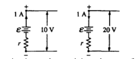
The figures above show parts of two circuits, each containing a
battery of emf ε and internal resistance r. The current in each
battery is 1 A, but the direction of the current in one battery is
opposite to that in the other. If the potential differences across the
batteries' terminals are 10 V and 20 V as shown, what are the values
of ε and r?
(A) E = 5 V, r = 15 Ω
(B) E =10 V, r = 100
Ω
(C) E = 15 V, r = 5 Ω
(D) E = 20 V, r = 10 Ω
(C)
What is the current through the 6.0 ꭥ resistor shown in the
accompanying circuit diagram? Assume all batteries have negligible
resistance.
(A) 0 A
(B) 0.40 A
(C) 1.3 A
(D)
1.5 A
(A)
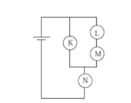
Rank the current through the bulbs.
(A) K > L > M >
N
(B) L = M > K = N
(C) L > M > K > N
(D) N
> K > L = M
(D)
Bulb K burns out. Which of the following statements is true?
(A)
Only bulb N goes out.
(B) Bulb N becomes brighter.
(C) The
brightness of bulb N remains the same.
(D) Bulb N becomes dimmer
but does not go out.
(D)
Bulb M burns out. Which of the following statements is true?
(A)
Only bulb M goes out.
(B) Bulb N goes out but at least one other
bulb remains lit.
(C) The brightness of bulb N remains the
same.
(D) Bulb N becomes dimmer but does not go out.
(D)
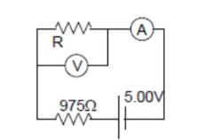
The voltmeter in the accompanying circuit diagram has internal
resistance 10.0 kꭥ and the ammeter has internal resistance 25.0 ꭥ. The
ammeter reading is 1.00 mA. The voltmeter reading is most
nearly:
(A) 1.0 V
(B) 3.0 V
(C) 4.0 V
(D) 5.0 V
(C)
When two resistors, having resistance R1 and R2, are connected in
parallel, the equivalent resistance of the combination is 5 ꭥ. Which
of the following statements about the resistances is correct?
(A)
Both R1 and R2 are greater than 5 ꭥ.
(B) Both R1 and R2 are equal
to 5 ꭥ.
(C) Both R1 and R2 are less than 5 ꭥ.
(D) The sum of
R1 and R2 is 5 ꭥ.
(A)
When a single resistor is connected to a battery, a total power P is
dissipated in the circuit. How much total power is dissipated in a
circuit if n identical resistors are connected in series using the
same battery? Assume the internal resistance of the battery is
zero.
(A) n2P
(B) nP
(C) P/n
(D) P/n2
(C)
In the accompanying circuit diagram, the current through the 6.0–ꭥ
resistor is 1.0 A. What is the power supply voltage V?
(A) 10 V
(B) 18 V
(C) 24 V
(D) 30 V
(D)
In the circuit diagrammed above, the 3.00–ꭥF capacitor is fully
charged at 18.0 ꭥC. What is the value of the power supply voltage
V?
(A) 4.40 V
(B) 6.00 V
(C) 8.00 V
(D) 10.4 V
(C)
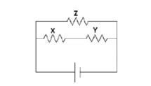
Given the simple electrical circuit above, if the current in all
three resistors is equal, which of the following statements must be
true?
(A) X, Y, and Z all have equal resistance
(B) X and Y
have equal resistance
(C) X and Y added together have the same
resistance as Z
(D) X and Y each have more resistance than Z
(C)
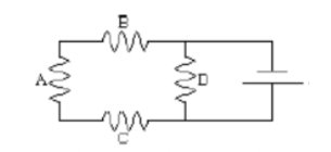
If all of the resistors in the above simple circuit have the same
resistance, which would dissipate the greatest power?
(A)
resistor A
(B) resistor B
(C) resistor C
(D) resistor D
(D)
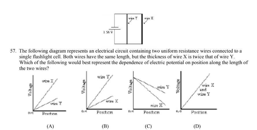
The following diagram represents an electrical circuit containing two
uniform resistance wires connected to a single flashlight cell. Both
wires have the same length, but the thickness of wire X is twice that
of wire Y.
Which of the following would best represent the
dependence of electric potential on position along the length of the
two wires?
(A)
(B)
(C)
(D)
(D)
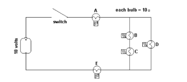
Five identical light bulbs, each with a resistance of 10 ohms, are
connected in a simple electrical circuit with a switch and a 10 volt
battery as shown in the diagram below. Which bulb (or bulbs) could
burn out without causing other bulbs in the circuit to also go
out?
(A) only bulb D
(B) only bulb E
(C) only bulbs C
or D
(D) bulbs B, C, or D
(A)
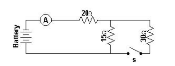
With the switch open, what would be the potential difference across
the 15 ohm resistor?
(A) 30 V
(B) 40 V
(C) 60 V
(D) 70 V
(A)
With the switch open, what must be the voltage supplied by the
battery?
(A) 30 V
(B) 40 V
(C) 60 V
(D) 70 V
(D)
When the switch is closed, what would be the current in the
circuit?
(A) 1.7 A
(B) 2.0 A
(C) 2.3 A
(D) 3.0 A
(C)
How would the current through the 2 ohm resistor compare to the
current through the 4 ohm resistor?
(A) twice as large
(B)
one–half as large
(C) equally as large
(D) four times as large
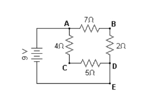
(C)
What would be the potential at point B with respect to point C in the
above circuit?
(A) +7 V
(B) +3 V
(C) 0 V
(D) –3 V
(D)
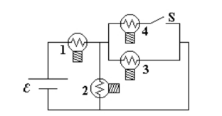
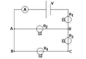
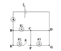
A circuit is connected as shown. All light bulbs are identical. When
the switch in the circuit is closed
illuminating bulb #4, which
other bulb(s) also become brighter?
(A) Bulb #1 only
(B)
Bulb #2 only
(C) Bulbs #2 and #3 only
(D) Bulbs #1, #2,
and #3
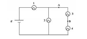
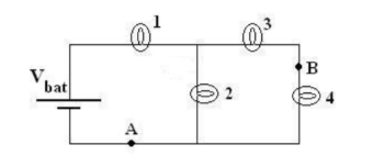
(A)
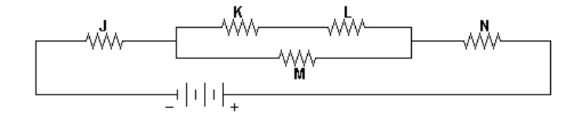
Through which resistor(s) would there be the greatest
current?
(A) M only
(B) N only
(C) J and N only
(D) K and L only
(C)
Which resistor(s) have the greatest rate of energy
dissipation?
(A) M only
(B) N only
(C) J and N only
(D) K and L only
(C)
The circuit shown has an ideal ammeter with zero resistance and four
identical resistance light bulbs which are initially illuminated. A
person removes the bulb R4 from its socket thereby permanently
breaking the electrical circuit at that point. Which statement is true
of the circuit after removing the bulb?
(A) The voltage from B →
C increases.
(B) The power supplied by the battery
increases
(C) The voltage across R1 increases.
(D) The
ammeter reading is unchanged.
(A)
A current through the thin filament wire of a light bulb causes the
filament to become white hot, while the larger wires connected to the
light bulb remain much cooler. This happens because:
(A)
the larger connecting wires have more resistance than the
filament.
(B) the thin filament has more resistance than the
larger connecting wires.
(C) the filament wire is not
insulated.
(D) the current in the filament is greater than that
through the connecting wires.
(B)
In the circuit above the voltmeter V draws negligible current and the
internal resistance of the battery is 1.0 ohm. The reading of the
voltmeter is
(A) 10.0 V
(B) 10.5 V
(C) 10.8 V
(D) 11.6 V
(C)
For the circuit shown, a shorting wire of negligible resistance is
added to the circuit between points A and B. When this shorting wire
is added, bulb #3 goes out. Which bulbs (all identical) in the circuit
brighten?
(A) Only Bulb 4
(B) Only Bulbs 1 and 4
(C)
Only Bulbs 2 and 4
(D) Bulbs 1, 2 and 4
(B)
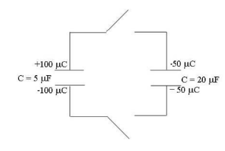
For the configuration of capacitors shown, both switches are closed
simultaneously. After equilibrium is established, what is
the
charge on the top plate of the 5 μF capacitor?
(A) 50 μC
(B) 30 μC
(C) 25 μC
(D) 10 μC
(D)
A student wants to make a brighter light bulb. He decides to modify
the filament. How should the filament of a light bulb be modified in
order to make the light bulb produce more light at a given
voltage?
(A) Increase the resistivity only.
(B) Increase the
diameter only.
(C) Decrease the diameter only.
(D) Decrease
the diameter and increase the resistivity.
(B)
For the circuit shown, the ammeter reading is initially I. The switch
in the circuit then is closed. Consequently:
(A) The ammeter
reading decreases.
(B) The potential difference between E and F
increases.
(C) Bulb #3 lights up more brightly.
(D) The
power supplied by the battery decreases.
(C)
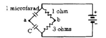
In the circuit shown above, the potential difference between points a
and b is zero for a value of capacitance C of
(A) 1/3 microfarad
(B) 2/3 microfarad
(C) 2 microfarads
(D) 3 microfarads
(A)
For the circuit shown, when a shorting wire (no resistance) connects the points labeled A and B, which of the numbered light bulbs become brighter? Assume that all four bulbs are identical and have resistance R .
(A) Bulb 1 only
(B) Bulb 2 only
(C) Bulb 3 only
(D)
Bulbs 1 and 3 only
(D)
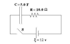
For the RC circuit shown, the resistance is R = 10.0 ꭥ, the
capacitance is C = 5.0 F and the battery has voltage ξ= 12 volts . The
capacitor is initially uncharged when the switch S is closed at time
t=0. At some time later, the current in the circuit is 0.50 A. What is
the magnitude of the voltage across the capacitor at that
moment?
(A) 5 volts
(B) 6 volts
(C) 7 volts
(D)
12 volts
(C)
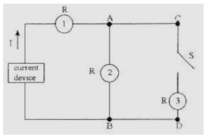
In the circuit shown above, a constant current device is connected to
some identical light bulbs. After the switch S in the circuit is
closed, which statement is correct about the circuit?
(A)
Bulb #2 becomes brighter.
(B) Bulb #1 becomes dimmer.
(C)
All three bulbs become equally brighter.
(D) The voltage between
points C and D is decreased.
(D)
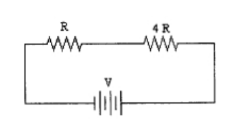
Two resistors, one with resistance R and the second with resistance 4R are placed in a circuit with a voltage V.
(A) 4 P
(B) P
(C) 1/2 P
(D) 1/4 P
(A)
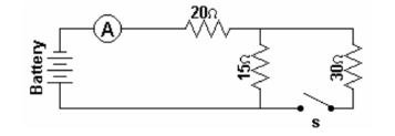
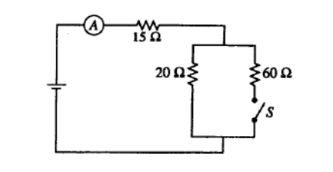
A battery, an ammeter, three resistors, and a switch are connected to
form the simple circuit shown above. When the switch is closed what
would happen to the potential difference across the 15 ohm
resistor?
(A) it would equal the potential difference across the
20 ohm resistor
(B) it would be twice the potential difference
across the 30 ohm resistor
(C) it would equal the potential
difference across the 30 ohm resistor
(D) it would be half the
potential difference across the 30 ohm resistor
(C)
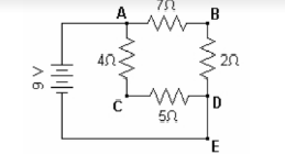
What would be the current at point E in the circuit?
(A) 2 amp
(B) 4 amp (C) 5 amp (D) 7 amp
(A)
What would be the potential at point B with respect to point
D?
(A) +2 V (B) +4 V (C) +5 V (D) +7 V
(A)
Two resistors and a capacitor are connected with a 10 volt battery, a
switch and an ideal ammeter to form the simple electrical circuit
shown. After the switch is closed and the current in the circuit
reaches a constant value, what is the reading on the ammeter in the
circuit?
(A) 8.1 × 10⁻²A
(B) 7.5 × 10⁻²A
(C) 6.9 ×
10–2A
(D) zero
(B)
When the switch is closed, what would be the current in the circuit
shown in the diagram above if the two batteries are opposing one
another?
(A) 0.75 A
(B) 0.5 A
(C) 0.3 A
(D) 0.2 A
(D)
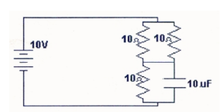
The diagram above shows an electrical circuit composed of 3 resistors
and 1 capacitor. If each resistor has a resistance of 10 Ω and the
capacitor has a value of 10 μF, what would be the charge stored in the
capacitor when an EMF of 10 V is maintained in the circuit for a
sufficient time to fully charge the capacitor?
(A) 23 μC
(B) 40 μC
(C) 67 μC
(D) 100 μC
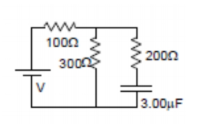
(C)
Given 4 identical resistors of resistance R, which of the following configurations would have an equivalent resistance of 4/3 R?
(A)
(B)
(C)
(D)
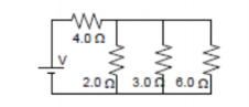
(A)
What would be the total current being supplied by the battery in the
circuit shown above?
(A) 3.0 amperes
(B) 2.0
(C) 1.5
amperes
(D) 1.0 amperes
(C)
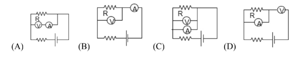
Which of the following wiring diagrams could be used to experimentally determine R using Ohm's Law? Assume an ideal voltmeter and an ideal ammeter.
(A)
(B)
(C)
(D)
(B)
Closing which of the switches will produce the greatest power
dissipation in R2?
(A) S1 only
(B) S2 only
(C) S1 and
S2 only
(D) S1 and S3 only
(C)
Closing which of the switches will produce the greatest reading on
the ammeter?
(A) S1 only
(B) S2 only
(C) S1 and S2
(D) S1 and S3 only
(D)
Closing which of the switches will produce the greatest voltage
across R3?
(A) S1 only
(B) S2 only
(C) S1 and S2 only
(D) S1 and S3 only
(A)