Electricity and magnetism | IGSCE Physics
Direction of field lines on a bar magnet.
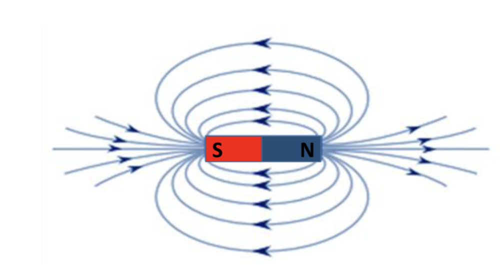
from north to south, effect of north on each
Induced magnetism
When a magnetic material becomes temporarily magnetised in the presence of a magnetic field.
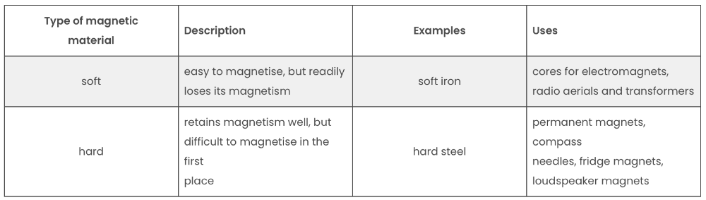
Types of magnetic materials and the type of magnets they create.
Magnetic field
A region in which a magnetic pole experiences a force.
State the difference between magnetic and non-magnetic materials
Magnetic materials can be magnetised or attracted to magnets. Non-magnetic aren't affected by magnetic fields.
How to show lines of bar magnet magnetic fields
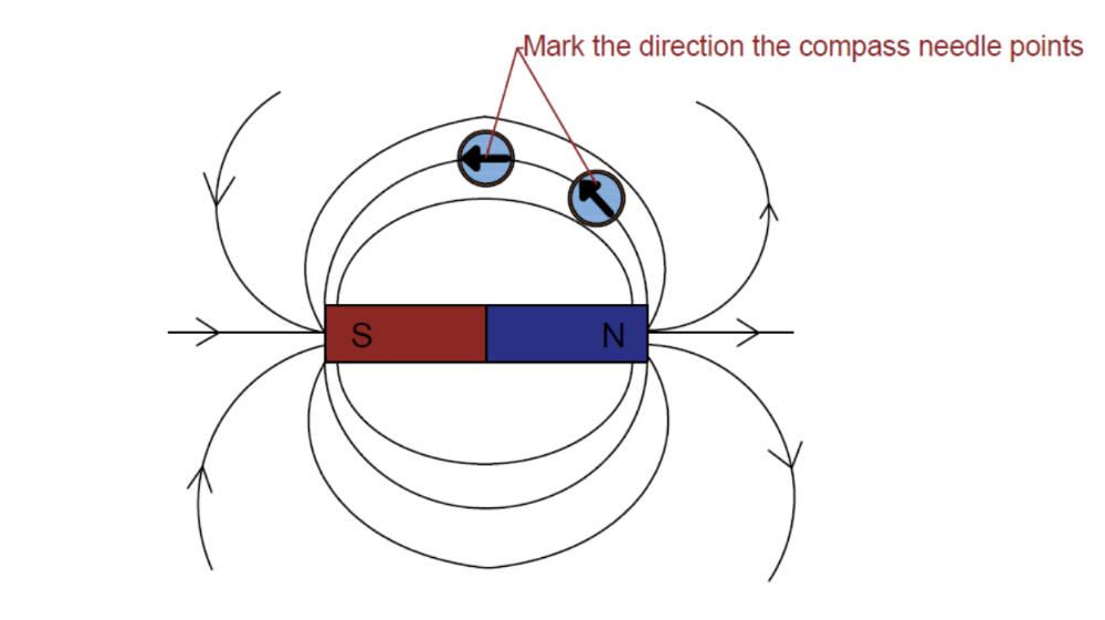
1. Place the plotting compass near the magnet on a piece of
paper
2. Mark the direction the compass needle points
3.
Move the plotting compass to many different positions in the magnetic
field, marking the needle direction each time
4. Join the points
to show the field lines.
Always points to South Pole
- Can also use iron fillings that congregate around where fields are strongest as are attracted and show te lines.
What are permanent magnets used in
Used in devices that require a stable magnetic field, such as in motors, Loudspeakers, door latches and Fridge magnets.
What are electromagnets magnets used in
Used where variable magnetism is needed, such as in cranes, Electric buzzers and bells and speakers, as they can be turned on and off by controlling the electric current.
How to increase strength of magnets
There is no way to change the strength of a permanent magnet, but there are three ways to increase the strength of an electromagnet:
1. Increase the current flowing through it: the greater
the current, the greater the strength of the field.
2. Increase
the number of turns of wire on the coil: this does not mean making
the foil longer, but packing more turns into the same space to
concentrate the field.
3. Add a soft iron core: an iron core
becomes strongly magnetised by the field, and this makes the whole
magnetic field much stronger.
How magnetic forces arise
Magnetic forces arise due to interactions between magnetic fields.
When two fields overlap, their interactions can cause either attraction or repulsion, depending on the field orientations, opposites attract etc.
What charge is measured in
coulombs (c)
Describe an electric field
a region in which an electric charge experiences a force
Describe experiments to show the production of electrostatic charges
- Inflate a balloon and rub it quickly on any dry surface e.g. a carpet. Then open a tap and hold the balloon next to it (without touching the water). You should see that the water bends towards the balloon!
- Tear up a piece of paper into small bits. Then take a ruler, rub it on your hair and place them just above the bits of paper, without touching them. You should see the paper get attracted to the ruler.
This kind of attraction is called electrostatic attraction. This happens because of the charges on the materials.
When insulating materials rub against each other they become electrically charged. Electron get ‘rubbed off’ one material and on to the other. The material that gains electrons becomes negatively charged. The material that loses electrons is left with a positive charge.
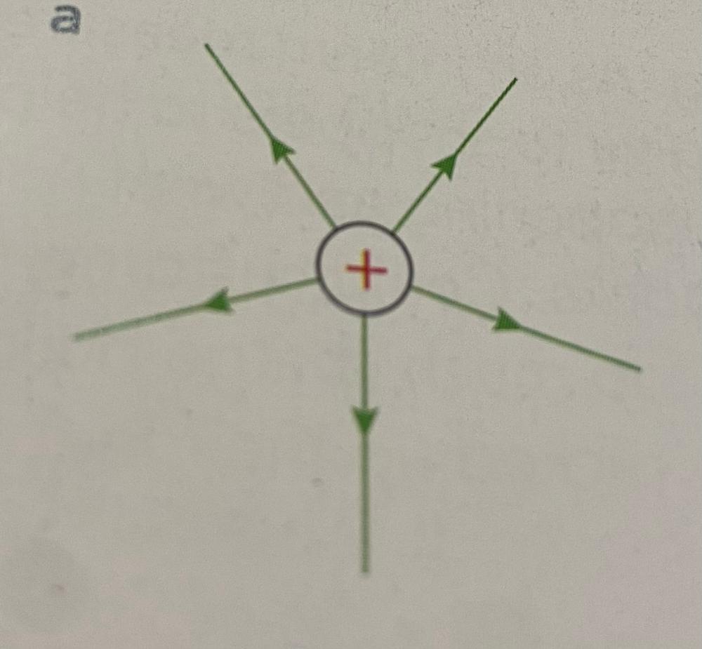
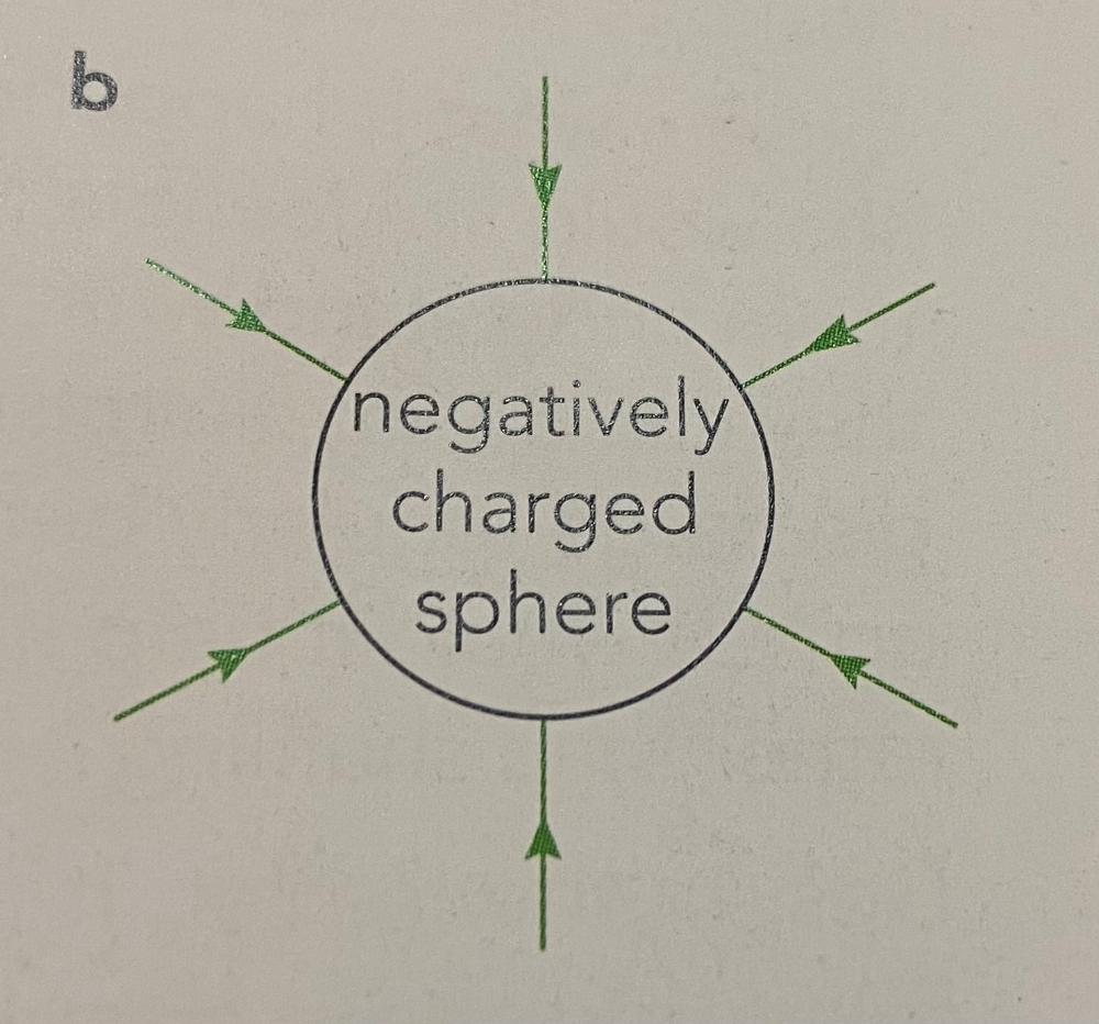
direction of electric field
the direction of an electric field at a point is the direction of the force on a positive charge at that point. away from positive and towards negative
Describe simple electric field patterns around a point charge
Describe simple electric field patterns around a charged conducting sphere
Describe simple electric field patterns between two oppositely charged parallel conducting plates

Describe an experiment to distinguish between electrical conductors and insulators
Set up a circuit with a light and a gap in the circuit where a material can be added with claw clips, if the light lights its a conductor, if not insulator.
Define electric current
Define electric current as the charge passing a point per unit time.
Current (I) = charge (Q) / time (t)
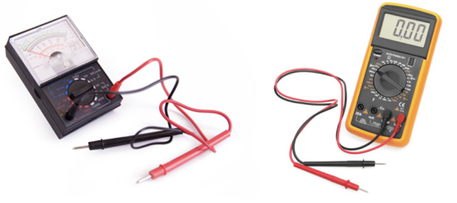
Describe the types of ammeters (analogue and digital) with different ranges
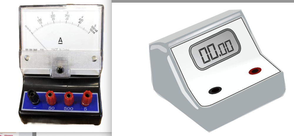
ammeter is used to measure electric current.
- Analogue Ammeter: Has a needle moving across a scale. Requires judgment for readings.
- To avoid parallax
error always read the meter from a position
directly
perpendicular to the scale. - Also they should be checked for zero errors before using
Digital Ammeter: display reading so less room for error.
Galvanometer: Measures very small currents and has a different symbol (needle- like arrow).
How to connect ammeter and unit
Connected in circuit correct way round so reading not backwards, measures in amperes /amps (A).
Direction of currents in circuit
Conventional current is from positive to negative and that the flow of free electrons is from negative to positive.
the difference between direct current (d.c.) and alternating current (a.c.)
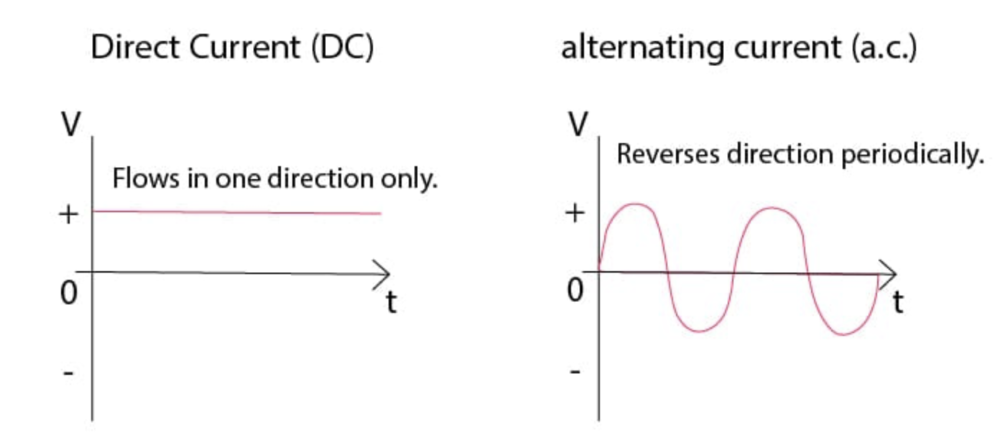
Direct Current (d.c.): Flows in one direction only.
• Found in batteries and most small electronic circuits.
Alternating Current (a.c.): Reverses direction periodically.
•Used in mains electricity (e.g., 50 Hz frequency means direction changes 100 times per second).
Define electromotive force (e.m.f.) and equation
the electrical work done by a source in moving a unit charge around a complete circuit (voltage across a source)
measured in volts (V)
e.m.f. (E) = work (W) / charge (Q)
Define potential difference (p.d.) and equation
Define potential difference (p.d.) as the work done by a unit charge passing through a component. ie.voltage between two points
measured in volts (V)
p.d. (V) = work (W) / charge (Q)
How to measure potential difference (p.d.)
With a voltmeter, (V) connected in parallel with component being measured
analogue or digital like ammeters with same errors and pros
the equation for resistance
R = V/I
Resistance = voltage / current
Describe an experiment to determine resistance using a voltmeter and an ammeter and do the appropriate calculations.
Measure voltage and current, then apply Ohm's Law to calculate resistance.
- Connect the component (e.g., a resistor) in series with a power supply and an ammeter.
- Connect the voltmeter in parallel across the component.
Turn on the power supply and record the current from the ammeter and resistance from voltmeter. Then use formula to calculate.
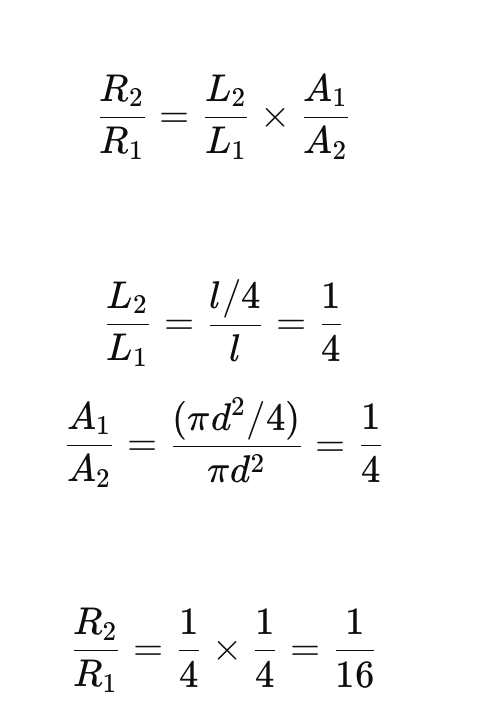
State the relationship of the resistance of a metallic wire to its length and to its cross-sectional area. and magnitude it effects
- Resistance is directly proportional to the length of the wire. A longer wire has higher resistance.
- Resistance is inversely proportional to the cross-sectional area of the wire. A larger cross-sectional area (thicker wire) results in lower resistance.
- Length (L) → directly proportional
- If you double the length, resistance doubles.
- Diameter
(d) → inversely proportional to the square
- If you double the diameter, resistance becomes ¼ (four times smaller).
- Increasing diameter reduces resistance much more powerfully than increasing length increases it.
Sketch and explain the current–voltage graphs for a resistor of constant resistance, a filament, lamp and a diode.
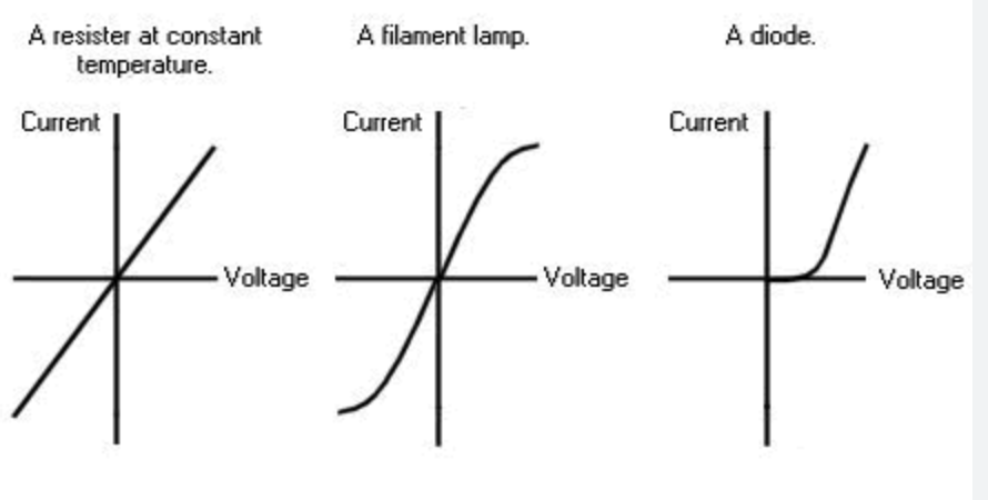
Resistor with Constant Resistance:
- Graph: A straight line passing through the origin.
- Explanation:The current is directly proportional to the voltage, meaning that for every increase in voltage, there is a corresponding proportional increase in current.This relationship is described by Ohm's Law.
Filament Lamp:
- Graph: A curved, non-linear graph.
- Explanation: As the voltage increases, the filament heats up the atoms to vibrate more vigorously, causing more frequent and forceful collisions with the free electrons that carry the electrical current. These collisions impede the flow of electrons, effectively increasing the resistance of the filament.
Diode:
- Graph:Non-linear with a distinct characteristic in the forward and reverse bias.
- Explanation:A diode allows current to flow easily in one direction (forward bias) and blocks current flow in the opposite direction (reverse bias).
Recall and use the equation for electrical power
P = IV
Power = current x voltage
Recall and use the equation for electrical energy or energy transferred
E = IVt
Energy transferred (J) joules = current x voltage x time
Define the kilowatt-hour (kW h) and calculate the cost of using electrical appliances where the energy unit is the kW h
- A unit of energy, representing the amount of energy used by a 1 kW appliance operating for 1 hour.
- Step 1: Determine the appliance's power rating in kilowatts (kW). Most appliances list this on a label or in the product manual.
- Step 2: Determine the time the appliance is used in hours.
- Step 3: Calculate kWh used: Multiply the power (kW) by the time (hours).
3. Calculating the Cost:
- Step 1: Determine the cost per kWh. This is typically found on your electricity bill or from your provider.
- Step 2: Calculate the total cost. Multiply the kWh used by the cost per kWh.
Cell and battery function and diagram
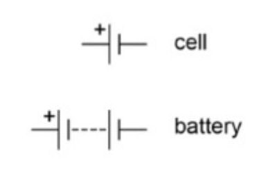
Cells are the basic units that provide electrical energy, converting stored chemical energy into electrical potential energy. Batteries are multiple cells connected together.They create a potential difference (voltage) that drives the flow of electric current.
Power Supplies diagrams and function
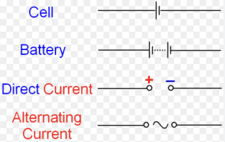
An electrical device that provides electrical energy to a circuit, converting electrical energy from a source to the desired voltage, current, and frequency to operate electrical components. It essentially acts as a source of electrical power, "pushing" the charge (current) through the circuit.
Generator definition
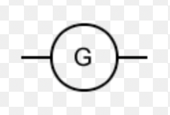
Generators convert mechanical energy into electrical energy, typically by rotating a coil of wire within a magnetic field.
Potential dividers definition and diagrams
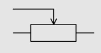
Potential dividers (or voltage dividers) are circuits that use resistors to create a specific voltage output from a higher input voltage.
Switches definition and diagrams
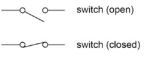
Switches are devices used to open or close a circuit, controlling the flow of current.
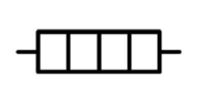
Types of resistors definition and diagrams

Resistors limit the flow of current in a circuit.
- Fixed resistors have a constant resistance, while variable resistors allow for adjustable current flow.
- Variable resistors: an electrical component that allows the resistance in a circuit to be adjusted. It works by changing the length of wire that the current flows through, thereby altering the resistance.
- Thermistors (NTC):Thermistors are resistors whose resistance changes with temperature. Negative Temperature Coefficient (NTC) thermistors have a resistance that decreases as temperature increases.
- Light-Dependent Resistors (LDRs): resistors that change their resistance based on the amount of light they receive. Their resistance decreases as light intensity increases.
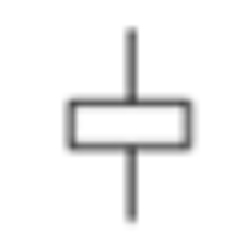
Heaters definition and diagrams
Heaters convert electrical energy into thermal energy, causing a temperature increase in the surrounding environment.
Motor definition and diagrams
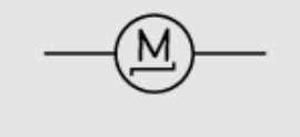
A component that converts electrical energy into mechanical energy.
Magnetising Coil definition and diagrams
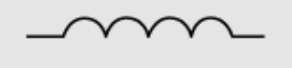
A coil of wire that creates a magnetic field when current flows through it.
Transformers definition and diagrams

Transformers are devices that transfer electrical energy between circuits through electromagnetic induction, typically using coils of wire.
Fuse definition and diagrams
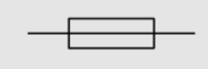
Fuses are safety devices designed to break a circuit if the current exceeds a certain level, protecting other components from damage.
Relay definition and diagrams
Relays are electrically operated switches that use a small current to control a larger current circuit.
Diode definition and diagrams

A diode only allows current to flow in one direction (the direction the triangle points in the symbol) and blocks it in the reverse direction
Light emitting diode definition and diagrams
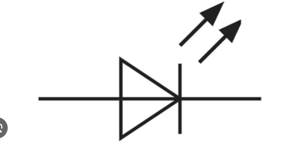
A type of diode that emits light when a current flows through it.
series and parallel circuit rules
- The current at every point in a series circuit is the same.
- The total p.d. of in a series circuit will be the sum of the p.d. across each component in the circuit.
- The total resistance in a series circuit is the sum of the resistance of all the resistors in the circuit.
- The current from the source, of a parallel circuit, is the sum of the separate branches in the circuit.
- The combined resistance of the resistors in a parallel circuit is less than that of the individual resistors because adding resistors in parallel provides more paths for current to flow, effectively reducing the overall resistance.
- the sum of the currents entering a junction in a parallel circuit is equal to the sum of the currents that leave the junction.
- In a parallel circuit, the potential difference (voltage) across all branches is the same, and equal to each other.
- Charge is conserved at a junction, with the total current flowing into the junction being the same as the total current flowing out of it in a parallel circuit.
- If you have a conductor carrying a steady current, and you increase its resistance, the voltage (p.d.) across it will also increase. due to v=IxR rule
Calculate the effective resistance of two resistors in parallel.
State the advantages of connecting lamps in parallel in a lighting circuit
-
- the voltage across each bulb will be the same, so every bulb will be equally bright
- each component is independent of other. In a series circuit, if one component breaks down, the entire circuit will be affected. But in a parallel circuit, there are multiple paths for the current to flow.
- Each component can be independently controlled by a switch. In a series circuit, one switch controls every component. In a parallel circuit, you can connect switches parallel for component in different branches, to turn them off or on.
Describe the action of a variable potential divider
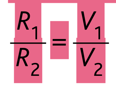
It consists of two resistors connected in series, with the output voltage taken from the junction between them. This setup splits the input voltage into smaller parts, with the division of voltage being proportional to the resistance values of the two resistors.
the wires in a mains circuit and which a switch has tube connected to
- The live wire carries the electrical current from the power source. The switch must be on the live wire to turn it off.
- Neutral Wire's Role:The neutral wire's function is to provide a return path for the current back to the power source. If the switch is on the neutral wire, the live wire remains connected to the appliance.
- Earth Wire's Role:The earth wire provides a safe path for fault currents to flow to the ground, preventing electric shock in case of a fault.
Use of trip switch and fuses
Trip switch: Often on fuse boxes. when current exceeds a certain value the switch trips breaking the circuit.
Fuse: A device that breaks the circuit of the current exceeds a limit. It is a piece of metal wire that melts when too much current flows through. Thicker wore lets more through.
rating of fuse should be just over the value of the current that flows though it when appliance is operating normally.
State the factors affecting the magnitude of an induced e.m.f
- The faster the movement, the higher the e.m.f.
- The stronger the magnets, the more the e.m.f. produced
- When the wire is coiled around several times, the no. of magnetic fields intersecting increases, and the current/voltage produced also increases.
Describe an experiment to demonstrate electromagnetic induction.
Apparatus Needed: A coil of wire, a magnet, and an ammeter.
Steps:
1. Connect the coil to the ammeter to form a complete
circuit.
2. Move the magnet into the coil. Observe the ammeter
needle deflecting, showing that a current is induced.
3. Move the
magnet out of the coil. The ammeter needle deflects in the opposite
direction, showing that the induced current reverses.
4. Hold the
magnet still inside the coil. The ammeter shows no deflection, meaning
no e.m.f. is induced.
Conclusion: An e.m.f. is only induced when there is relative motion between the magnet and the coil.
Directions of induced current (e.m.f.)
Lenz's law - the direction of an induced e.m.f. opposes the change causing it.
If bring magnet to a coil the current will create a field that repels it, and if taking it away the current will attract it.
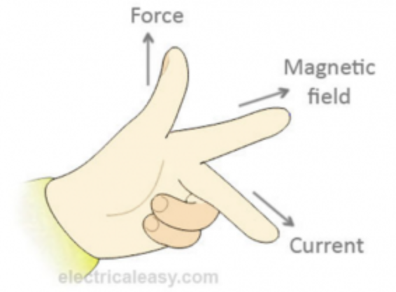
Fleming's Right-Hand Rule:
Used when dealing with electric generation
• Thumb: Direction of Force (Motion of the conductor).
•
Index Finger: Direction of the Magnetic Field
• Middle Finger:
Direction of the Induced Current.
How to Use:
1. Point your index finger in the direction of
the magnetic field ( to North).
2. Point your thumb in the
direction the conductor is moving.
3. Your middle finger will
point in the direction of the induced current.
Describe a simple form of a.c. generator
An a.c. generator converts mechanical energy into alternating electrical energy by electromagnetic induction. A simple generator consists of either a rotating coil in a magnetic field or a rotating magnet near a fixed coil.
- The direction of the induced e.m.f. changes every half turn of the coil, producing an alternating current (a.c.).
- The slip rings allow continuous rotation of the coil while the brushes allow it to maintain electrical contact with the external circuit.
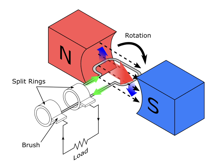
Describe a simple form of d.c. generator

- current in the left hand part of the coil causes a downward force and current in the right hand part of the coil causes an upward force. The coil rotates anti-clockwise because of the forces describe above.
When the coil is vertical, it moves parallel to the magnetic field, producing no force. This would tend to make the motor come to a stop, but two features allow the coil to continue rotating:
- the momentum of the motor carries it round
- A DC motor uses a split-ring commutator and brushes to direct current flow. The commutator is a rotating ring, split into segments, which reverses the current direction in the coil every half-turn. The brushes, which are typically made of carbon, maintain contact with the commutator and provide a path for current to flow in and out of the motor's coil.
Sketch and interpret graphs of e.m.f. for simple a.c. generators and relate the position of the generator coil to the peaks, troughs and zeros.
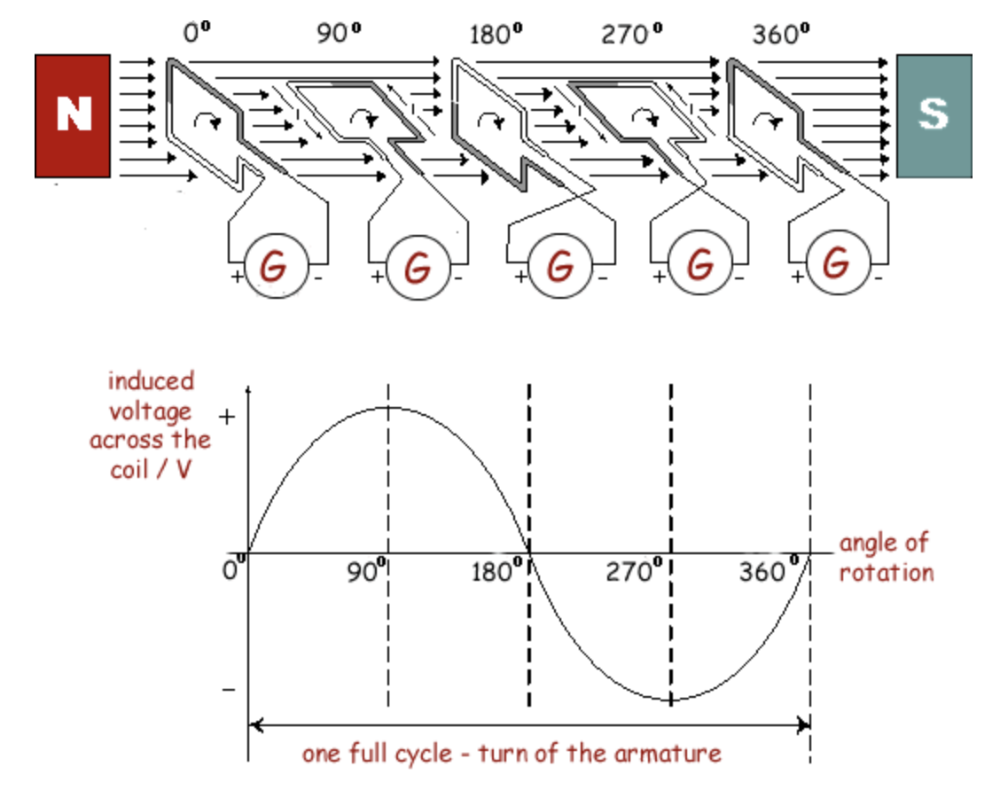
- peak positive e.m.f. → coil is horizontal (cutting magnetic lines at maximum rate).
- Peak negative e.m.f. → coil moves in opposite direction.
- 0 when the coil is moving perpendicular to the field (vertical)
Pattern and direction of the magnetic field due to current in straight wires
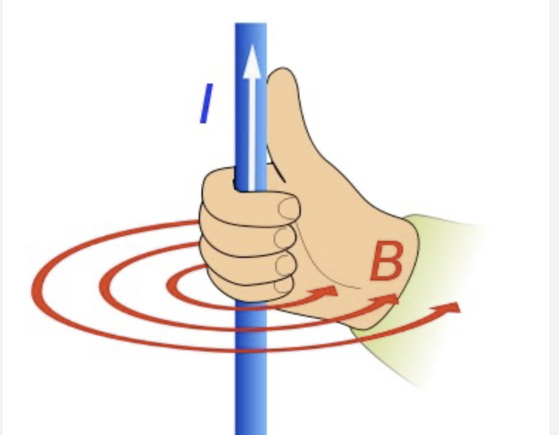
Wire has circular magnetic field around it with stronger nearest wire. Grab wire with right hand with thumb in direction of current to find direction of these field lines.
Pattern and direction of the magnetic field due to current in solenoids
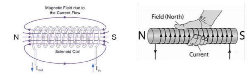
To determine North of solenoid wrap right hand fingers in direction of current and thumb will point to north.
how the magnetic effect of a current is used in loudspeakers
- Loudspeakers contain a coil of wire (voice coil) placed within a permanent magnetic field.
- When an alternating current flows through the voice coil, it creates a magnetic field that interacts with the permanent magnet.
- Vibration and sound production:This interaction generates a force on the coil, causing it to move back and forth.
- Cone movement:The coil is attached to a cone, which vibrates due to the coil's movement.
- Sound waves:These vibrations create pressure variations in the air, producing sound waves.
- Examples:Loudspeakers are used in all types of audio devices, including headphones, stereos, and public address systems.
What changes magnetic filled strength of solenoid
- Current:Increasing the current flowing through the solenoid directly increases the magnetic field strength.
- Number of Turns:A greater number of turns in the solenoid, especially within a fixed length (higher turn density), results in a stronger magnetic field.
- Core Material:Inserting a ferromagnetic core, like iron, into the solenoid significantly amplifies the magnetic field due to the alignment of magnetic domains within the core.
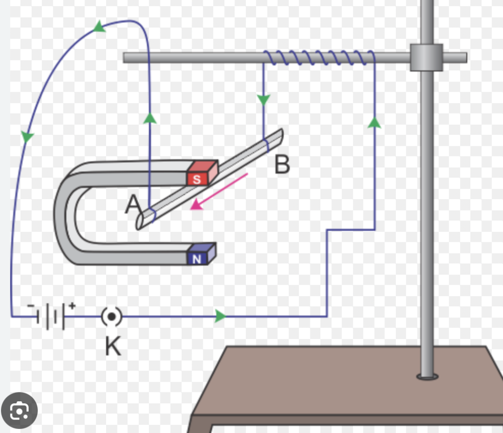
Describe an experiment to show that a force acts on a current-carrying conductor in a magnetic field, including the effect of reversing: how to calculate which way it will shift.
-
Setup:
- Use a strong horseshoe magnet.
- Suspend a conducting wire (e.g., copper wire) between the poles of the magnet so that the wire is perpendicular to the magnetic field lines.
- Connect the wire to a power supply and a switch to control the current.
-
Reversing the current:
- Reverse the connections of the wire to the battery. This will reverse the direction of the current flow.
- Observe that the direction of the wire's movement also reverses.
-
Reversing the magnetic field:
- Without changing the current direction, reverse the poles of the magnet.
- Observe that the wire's direction of movement reverses again.
- Thumb: Point your thumb in the direction of the conventional current (from positive to negative).
- Fingers: Point your fingers in the direction of the magnetic field lines.
- Force: Your palm indicates the direction of the force on the conductor, which is the direction it will shift.
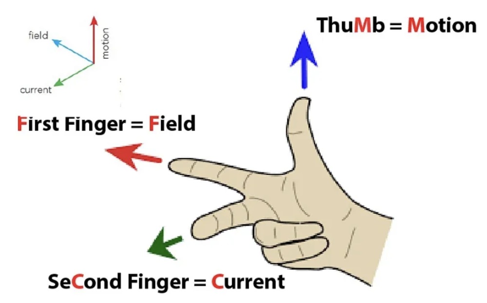
Fleming's Left-Hand Rule
Done when dealing with electric motors.
- First Finger (Forefinger): Point your first finger in the direction of the magnetic field lines (North to South).
- Second Finger (Middle Finger): Point your second finger in the direction of the conventional current (from positive to negative).
- Thumb: Your thumb will then indicate the direction of the force on the conductor.
The current is the positively charged and the flow of electrons (negative particles is opposite this)
Turning effect in a motor is increased by:
The turning effect can be increased by increasing the:
- number of coils of wire
- current
- strength of the magnetic field
simple transformer, describe
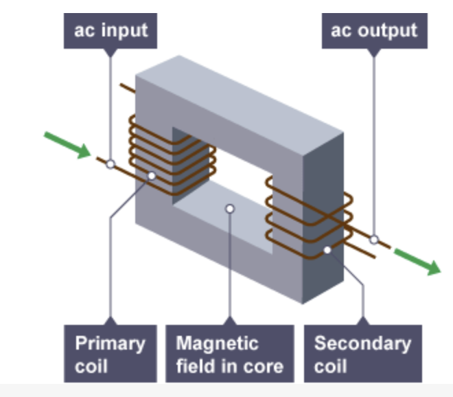
Alternating current goes through primary coil therefor its an electromagnet and produces a alternating magnetic field, this goes to the secondary coil through the core which allows a current to be generated. If its stepped up or down depends on wether number of coils has increased on the second coil or reduced.
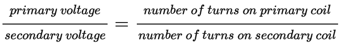
Equation for transformer voltage and turns on coil.
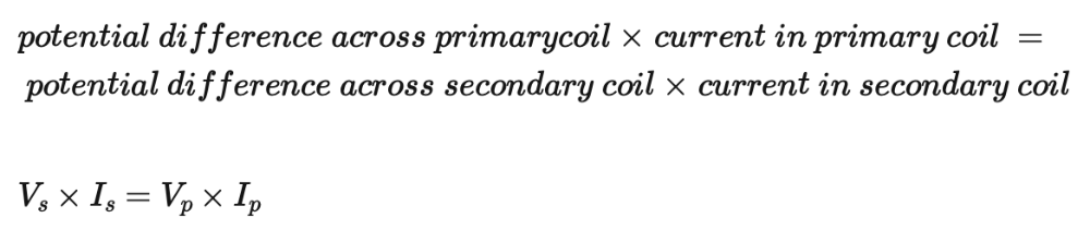
Recall and use the equation for 100% efficiency in a transformer
Equation for power loss in a cable, why higher voltage better, when used
High voltage means lower current and lower current means less energy transferred to surroundings by heating and less wasted as well as safer. This is why higher voltage better.
Step-up transformers can be used to increase the voltage from power stations to thousands of volts, which lowers the current in the transmission cables. Step-down transformers are then used to decrease the voltage from the transmission cables, so it is safer to distribute to homes and businesses.
combined resistance of resistors in parallel
1/combined resistance = 1/R1 + 1/R2
then after adding find the reciprocal to get the combined resistance
chsznge in resistance