Instructions for Side by Side Printing
- Print the notecards
- Fold each page in half along the solid vertical line
- Cut out the notecards by cutting along each horizontal dotted line
- Optional: Glue, tape or staple the ends of each notecard together
Chapter 3 Transducers - Notes
front 1 Q-factor formuala | back 1 operating frequency/bandwidth |
front 2 fractional bandwidth formula | back 2 bandwidth/operating frequency |
front 3 Bandwidth formula | back 3 max frequency - min frequency |
front 4 SPL | back 4 SPL = nc/f |
front 5 NZL | back 5 NZL = (D^2 * f) / 6 |
front 6 speed of crystal | back 6 c = fo * (2 * thickness) |
front 7 Operating frequency formula | back 7 fo = c/(2*thickness) |
front 8 thickness formula | back 8 thickness = c/(2*fo) |
front 9 Axial Resolution formula | back 9 1/2 SPL |
front 10 If a transducer diameter is doubled, what happens to the NZL? | back 10 If a transducer diameter is doubled, the near zone length will quadruple? |
front 11 If a transducer diameter is doubled, what happens to the depth of the focus? | back 11 If a transducer diameter is doubled, the focus is 4 times as deep. |
front 12 If the operating frequency is doubled, what happens to the NZL? | back 12 If the operating frequency is doubled, the NZL is doubled. |
front 13 focus beamwidth formula | back 13 focus beamwidth = 1/2 transducer diameter |
front 14 True or False?
| back 14 False
|
front 15 Transducer | back 15 device that converts energy from one form to another |
front 16 electric motor | back 16 electricity to kinetic |
front 17 people | back 17 chemical to kinetic |
front 18 light bulb | back 18 electricity to light (heat) |
front 19 Sound transducer | back 19 converts electricity to sound & vice versa |
front 20 Audible transducer | back 20 speaker - electricity to sound
|
front 21 amber - fossilized plant resin
| back 21 naturally occurring Piezoelectric materials |
front 22 ceramics - lead zirconate titanante (PZT)
| back 22 Man-made piezoelectric material |
front 23 ferroelectric material | back 23 piezoelectric material |
front 24 Piezoelectric principle | back 24 applied pressure (echo) comes back to the transducer, converted to electric energy. |
front 25 Reverse Piezoelectric principle | back 25 when a matter is deformed by an applied voltage it produces a pulse.
|
front 26 What is the most commonly used piezoelectric material in U/S? | back 26 ceramics - lead zirconate titanante (PZT) |
front 27 PZT | back 27 Piezoelectric element |
front 28 ceramic | back 28 Piezoelectric element |
front 29 crystal | back 29 Piezoelectric element |
front 30 element | back 30 Piezoelectric element |
front 31 Creation of Piezoelectric material | back 31 Heat to currie point
|
front 32 polling | back 32 placing a material in a very strong electrical field while the material is at a high temperature |
front 33 curie point | back 33 360 degrees
|
front 34 Heat sterilize | back 34 Never
|
front 35 when electricity is applied to PZT | back 35 vibrates then creates a mechanical longitudinal wave |
front 36 Increases & decreases in alternating current change the voltage within the crystal | back 36 Piezoelectric Effect |
front 37 One cycle of the operating (drive) voltage creates how many U/S pulses | back 37 2 or 3 |
front 38 How many cycles of (drive) voltage is required for Doppler? | back 38 5 to 30 |
front 39 Placing a material in a very strong electric field while the material is at a high temperature.
| back 39 A) poling |
front 40 Frequency of the driving voltage | back 40 equals the voltage of the sound produce by the transducer |
front 41 preferred frequency | back 41 voltage of the sound produce by the transducer |
front 42 operating frequency | back 42 voltage of the sound produce by the transducer |
front 43 resonant frequency | back 43 voltage of the sound produce by the transducer |
front 44 natural frequency | back 44 voltage of the sound produce by the transducer |
front 45 What 2 things determine operating frequency | back 45 propagation speed of material - 4 to 6 mm/μs
|
front 46 propagation speed of material | back 46 4 to 6 mm/μs |
front 47 thickness of the transducer | back 47 .2 - 1 mm |
front 48 thickness formula | back 48 thickness = .5λ |
front 49 wavelength formula | back 49 λ = c/f |
front 50 thickness (f) | back 50 thickness = .5c/f |
front 51 Relationship between thickness and frequency | back 51 inverse |
front 52 Relationship between thickness and wavelength | back 52 direct |
front 53 pulses per second | back 53 PRF |
front 54 voltage pulses per second | back 54 VRF |
front 55 relationship between PRF & VRF | back 55 PRF = VRF |
front 56 formula Pd | back 56 pd = nt |
front 57 SPL formula | back 57 SPL = nλ
|
front 58 Dampening | back 58 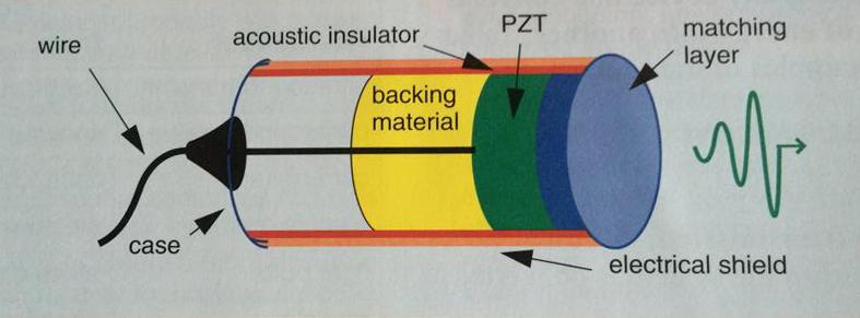 material placed behind the element which reduces # of cycles, Pd & SPL |
front 59 What is dampening material made of | back 59 epoxy resin + tungstun
|
front 60 What is the purpose of damping material? | back 60 short pulses create better images
|
front 61 dampening and axial resolution | back 61 dampening improves axial resolution |
front 62 dampening and amplitude | back 62 dampening reduces amplitude |
front 63 dampening and sensitivity | back 63 dampening decreases sensitivity |
front 64 dampening and efficiency | back 64 dampening decreases efficiency |
front 65 dampening and SPL | back 65 dampening decreases SPL |
front 66 dampening and Pd | back 66 dampening decreases Pd |
front 67 Which of the following is positive?
| back 67 B) decrease # of cycles |
front 68 impedance | back 68 propagation speed * density |
front 69 what is the purpose of gel? | back 69 without gel 80% of intensity of a pulse is reflected off the skin
|
front 70 Matching layer | back 70  matching layer eliminates loss from reflection at the surface of the transducer |
front 71 matching layer thickness formula | back 71 thickness = .25λ
|
front 72 list impedance from highest to lowest | back 72 element > matching layer > gel > skin |
front 73 impedance of matching layer | back 73 halfway between element and skin
|
front 74 What determines the matching layer λ?
| back 74 A) c/f |
front 75 Matching layer thickness .25λ.
| back 75 A) operating pulse |
front 76 Matching layer thickness .25λ.
| back 76 C) matching layer material |
front 77 What type of transducers do not need damping? | back 77 continuous wave
|
front 78 what is most desirable to get the maximum sound into the tissue?
| back 78 B) multiple matching layers |
front 79 Bandwidth | back 79  range of frequencies the transducer produces |
front 80 bandwidth determined by | back 80 transducer and the machine electronics |
front 81 relationship between Pd and bandwidth | back 81 inverse |
front 82 bandwidth formula | back 82 max frequency - min frequency |
front 83 middle frequency | back 83 center frequency |
front 84 fractional bandwidth formula | back 84 bandwidth/operating frequency |
front 85 Q factor | back 85 operating frequency/bandwidth |
front 86 relationship between Q factor and bandwidth | back 86 inverse |
front 87 Quality factor | back 87 unitless # describing the degree of damping
|
front 88 low Q transducers | back 88 imaging transducers
|
front 89 How many pulses in Q factor | back 89 1-3 |
front 90 when are transducers broadband? | back 90 fractional bandwidth is greater than 80% |
front 91 Broadband transducers are ___________ sensitive. | back 91 less |
front 92 Why are broadband transducers less sensitive | back 92 due to damping |
front 93 The highest frequency is 6 MHz. The lowest frequency is 2 MHz. What is the bandwidth?
| back 93 C) 4
|
front 94 The highest frequency is 6 MHz. The lowest frequency is 2 MHz. if the center frequency is 4 what is the fractional bandwidth?
| back 94 A) 1
|
front 95 Advantages of Broad bandwidth | back 95 *Multi-Hz transducers can be used
|
front 96 Types of Resolution | back 96 Detail
|
front 97 Detail resolution | back 97 ability to detail fine detail
|
front 98 What is detail resolution dependent on? | back 98 axial resolution
|
front 99 Axial resolution | back 99 ability to distinguish between two objects that lie next to each other in the depth plane. |
front 100 Which is frequently better axial or lateral resolution? | back 100 axial resolution |
front 101 What is axial resolution dependent on? | back 101 SPL |
front 102 Synonyms for axial resolution | back 102 longitudinal resolution
|
front 103 Units of axial resolution | back 103 mm |
front 104 How does SPL improve axial resolution? | back 104 shortening the pulse length prevents the echoes from combining as they return to the transducer |
front 105 How to improve axial resolution? | back 105 higher frequency
|
front 106 Lateral resolution | back 106 minimum distance that two objects can lie side by side and still be seen as two objects |
front 107 synonyms for lateral resolution | back 107 angular resolution
|
front 108 What is the prime factor for lateral resolution | back 108 beam width |
front 109 lateral resolution varies with depth.
| back 109 at the focus or near zone. |
front 110 Units of lateral resolution | back 110 mm |
front 111 Symbol for lateral resolution | back 111 R L |
front 112 primary method of reducing beam width | back 112 focusing. |
front 113 How does focusing improve lateral resolution? | back 113 by decreasing beam width |
front 114 Contrast resolution | back 114 the ability to see structures with different reflection intensity values as separate items. |
front 115 Detail resolution is dependent on? | back 115 amount of memory
|
front 116 Does urine have low or high impedance mismatch? | back 116 Low |
front 117 Does bone have low or high impedance mismatch | back 117 high |
front 118 SPL a function of | back 118 pulse duration
|
front 119 SPW a function of | back 119 crystal diameter |
front 120 Partial thickness artifact
| back 120 (thickness) due to 3D aspect of transducer |
front 121 Temporal resolution | back 121 the ability to accurately located moving structures at any particular instant in time.
|
front 122 Temporal resolution is dependent in time | back 122 Frame rate
|
front 123 SPL
| back 123 B) The ability to see two items above and below each other as separate items |
front 124 Huygens Wavelet | back 124 Produced by a tiny source
|
front 125 Huygens Principle | back 125 According to Huygens the hourglass shape of a sound beam is the result of constructive and destructive inference of many sound wavelets |
front 126 Aperture | back 126 width of the beam
|
front 127 near zone | back 127 is the area from the transducer to the focus.
|
front 128 focus | back 128 the smallest part of the beam
|
front 129 far zone | back 129 the area of divergence
|
front 130 What shape are sound waves produced by imaging transducers? | back 130 hourglass |
front 131 What is the Fresnel zone? | back 131 Near zone |
front 132 What is the Fraunhofer zone? | back 132 far zone |
front 133 When does the beam stop divergence? | back 133 when it reaches its original size |
front 134 What does width determine? | back 134 lateral resolution |
front 135 What changes top to bottom? | back 135 lateral resolution |
front 136 The width perpendicular to the scan plane determines what? | back 136 section thickness artifact. |
front 137 Formula for axial resolution | back 137 1/2 SPL |
front 138 Grating lobes | back 138 Significant intensity that travels out in some direction not included in the beam |
front 139 What type of transducer causes grating lobes? | back 139 Array |
front 140 What type of transducer causes side lobes | back 140 single element transducers |
front 141 What are some other names for near field? | back 141 focal length
|
front 142 What happens to the near field when you increase diameter? | back 142 increases |
front 143 What happens to the near field when you increase frequency? | back 143 increases |
front 144 NZL formula | back 144 Focal zone length
|
front 145 f 5 MHz d 5mm? 1 NZL
| back 145 F) 2 cm
|
front 146 What is the relationship between near zone length and diameter? | back 146 direct |
front 147 What is the relationship between near zone length and frequency? | back 147 direct |
front 148 For and unfocused beam where are the intensities the highest? | back 148 at the focus |
front 149 For and unfocused beam at any given point, Beam diameter is dependent on what? | back 149 frequency
|
front 150 When frequency is low beam divergence is __________. | back 150 wide |
front 151 When frequency is high beam divergence is __________. | back 151 narrow |
front 152 When diameter is high beam divergence is __________. | back 152 narrow |
front 153 When diameter is low beam divergence is __________. | back 153 wide |
front 154 Does a smaller frequency gives a shorter or longer near zone? | back 154 shorter |
front 155 variable aperture | back 155 increases # of elements fired |
front 156 What is the relationship between Beam divergence and frequency? | back 156 indirect |
front 157 What is the relationship between Beam divergence and diameter? | back 157 indirect |
front 158 Name the 3 way to focus a transducer | back 158 * curve the face
|
front 159 What type of focusing are the following?
| back 159 fixed
|
front 160 Focal region | back 160 an area on either side of the focal point which is within 25& or 6 dB of SPL |
front 161 Focused transducers and lateral resolution | back 161 worst lateral resolution due to mechanical focusing |
front 162 what is the value of focusing? | back 162 to improve resolution |
front 163 What improves lateral resolution? | back 163 decrease size of focal zone
|
front 164 Automatic scanning | back 164 method by which transducers rapidly collect information
|
front 165 What are the two ways rapid motion is accomplished in real time scanning? | back 165 Mechanically
|
front 166 Mechanical Motion in fixed focus | back 166 mechanical steering has to fo with curvature of PZT |
front 167 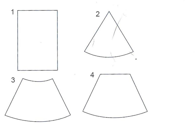 | back 167 1. linear array
|
front 168 Electronic scanning sequence | back 168 because elements are fixed focus is fixed
|
front 169 During electronic scanning phasing
| back 169 right |
front 170 What does phasing control? | back 170 beam direction
|
front 171 Haygens law | back 171 multiple spherical wavelengths create a wave form produce a wave and the wave travels in a direction - orthogonal to the wave form. |
front 172 where are electronic phased delay patterns produced? | back 172 in the beam former |
front 173 how does phasing control aperture? | back 173 some electricity is turned off. This changed the size of the element |
front 174 How is focus changed with phasing? | back 174 by curving the pattern |
front 175 phasing
| back 175 shallow |
front 176 Vector | back 176 sector with flat top
|
front 177 Annular array | back 177 multiple circular elements with wobble motor sweeps across |
front 178 What format are annular arrays displayed in? | back 178 sector |
front 179 Annular arrays
| back 179 mechanical |
front 180 Annular arrays
| back 180 electronic |
front 181 dynamic apodization | back 181 changing the amplitude as focusing & steering changes to decrease grating lobe |
front 182 dynamic focusing | back 182 delay correction is changed "on the fly"
|
front 183 dynamic aperture | back 183 using more or less elements to change the diameter of the entire face. |