Image Receptor Size: 10 x 12
SID: 40"
Patient
position
1) Patient is supine
2) Center the image receptor
1/2" below to the apex of the patella
3) Femoral epicondyles
are parallel to the image receptor
4) Shield gonads
Central
Ray
• Directed to a point 1/2 inferior to the apex of the
patella
• Perpendicular for a sthenic patient (19-24cm)
•
3-5 degrees cephalic for hypersthenic (greater than 24cm)
• 3-5
degrees caudad for hyposthenic (less than 19cm)
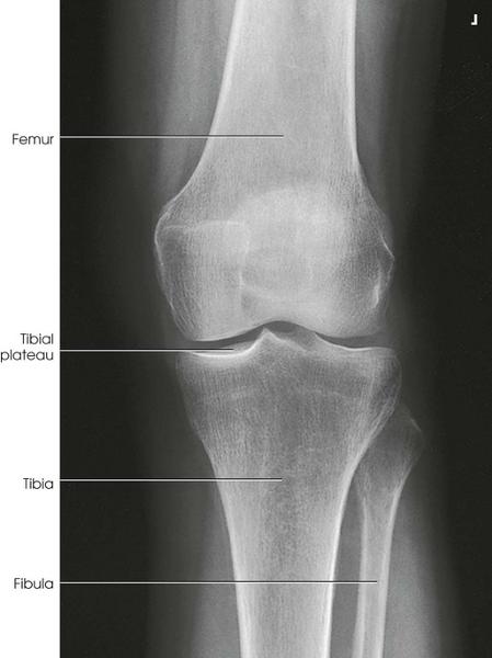
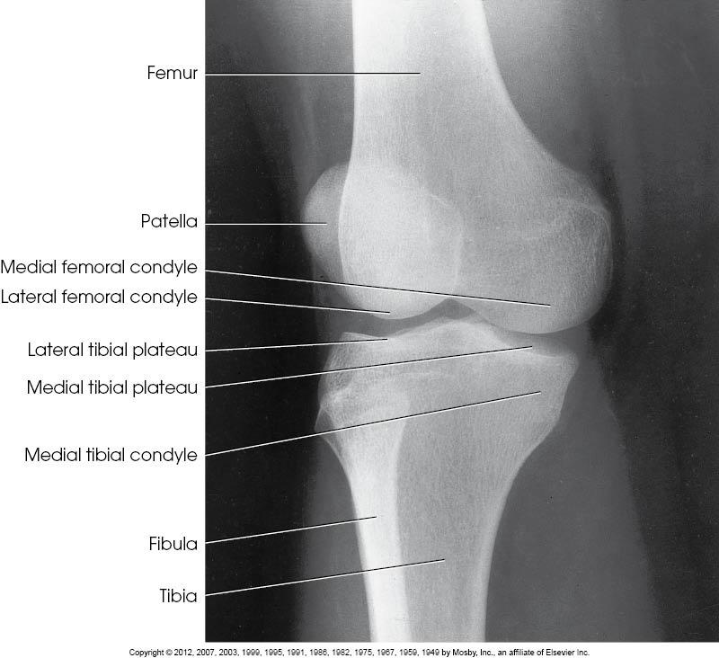
Structures
Shown
• Open knee joint
• Patella superimposed on
femur
• Soft tissue
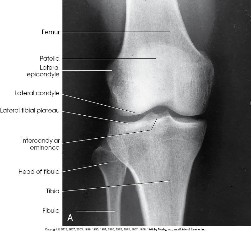
AP of the Knee
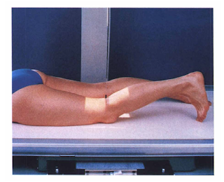
Image Receptor Size: 10 x 12
SID: 40"
Patient
position
1) Patient is prone
2 )Center the image receptor
1/2" below the apex of the patella
3) Femoral epicondyles
are parallel to the image receptor
4) Shield gonads
Central
Ray
• 5-7 degrees caudad to exit 1/2" below the patellar
apex
Structures Shown
• Open knee joint
• Patella
superimposed on femur
• Soft tissue
PA of the Knee
Image Receptor Size: 10 x 12
SID: 40"
Patient
position
1) Patient turns onto affected side
2) Flex the
knee about 20-30 degrees
3) Center the image receptor to the knee
joint (approximately 1" distal to the medial femoral
condyle)
4) Femoral epicondyles and patella are perpendicular to
the image receptor
5. Shield gonads
Central Ray
• 5-7
degrees cephalic centered 1" distal to the medial epicondyle
(opens joint space)
Structures Shown
• Femoral condyles
superimposed
• Open knee joint
• Patella in a lateral
profile with an open
• Soft tissue
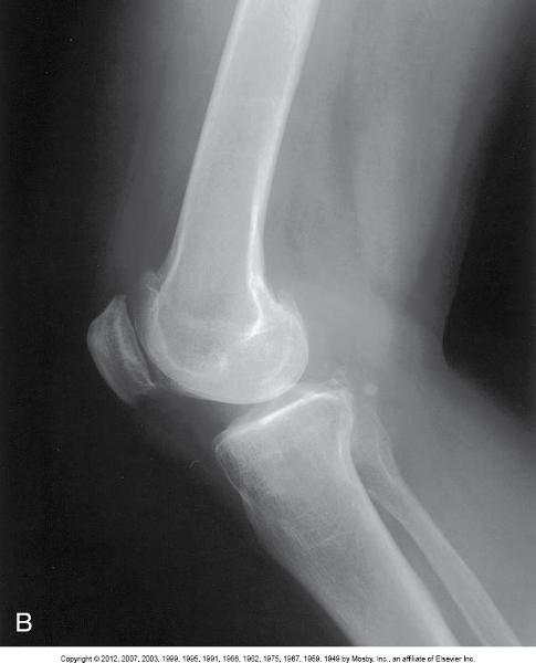
Lateral of the Knee, Mediolateral
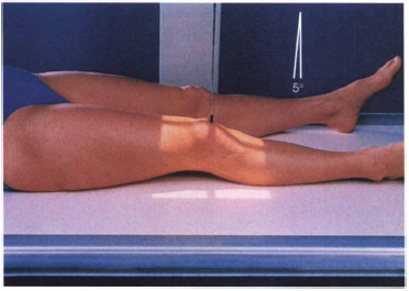
Image Receptor Size: 10 x 12
SID: 40"
Patient
position
1) Patient supine
2) Center the image receptor
1/2" below the patellar apex
3) Rotate the knee
laterally
4) Shield gonads
Central Ray
• Perpendicular
(or same angulation as AP knee) to the knee joint 1/2" below
apex
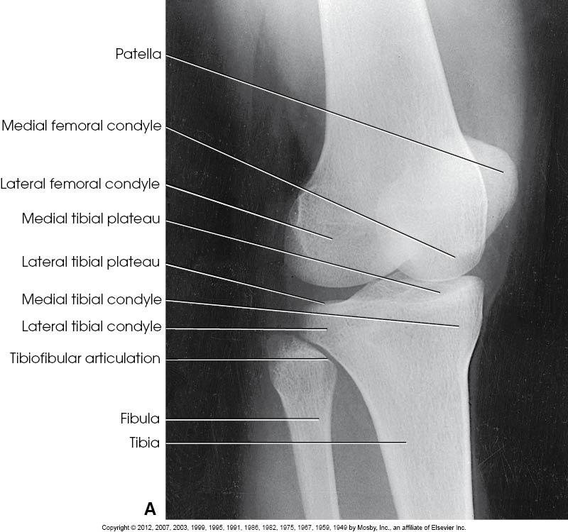
Structures Shown
• Patella projected slightly over the
border of the lateral femoral condyle
• Open knee joint
•
Tibial plateau
• Soft tissue
AP Oblique of the knee, Lateral rotation

Image Receptor Size: 10 x 12
SID: 40"
Patient
position
1) Patient is supine
2) Center the image receptor
1/2" below the patellar apex
3. Rotate the knee medially 45
degrees
4) Shield gonads
Central Ray
• Perpendicular
(or same angulation as AP knee) to the knee joint 1/2" below
apex
Structures Shown
• Open proximal tibiofibular
joint
• Tibial plateau
• Open joint space
• Patella
projected slightly over the border of the medial femoral
condyle
• Soft tissue
AP Oblique of the knee, Medial rotation

Image Receptor Size: 10 x 12
SID: 40" UPRIGHT
Patient
position
1) Patient is standing with their back against the
upright grid device
2) Center the knees to the image receptor
with no rotation. Toes straight ahead
3) Center of the image
receptor is at the knee joints - 1/2" below apex of the
patella
4) Shield gonads
Central Ray
• Horizontal and
perpendicular 1/2" below the apices of the patellas and midway
between the knees
Structures Shown
• Both knees on one
exposure
• *May reveal a narrowing of the joint spaces which may
appear normal without weightbearing - especially on arthritic patients*
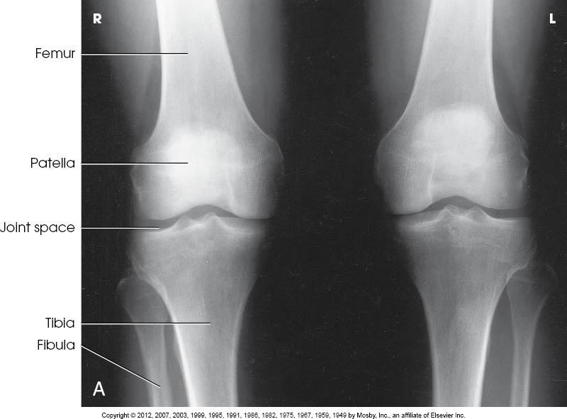
AP of the knee, Weightbearing
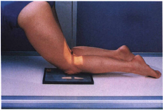
Image Receptor Size: 8 x 10
SID: 40"
Patient
position
1) Patient may be:
a. standing with affected knee
resting on a stool
b. standing with the knee in contact with the
front
c. kneeling on the table
2) Center the image receptor
to the apex of the patella
3) Knee is flexed 70 degrees from full
extension
4) Shields gonads
Central Ray
•
Perpendicular to the knee joint
Structures Shown
• Open
intercondyloid fossa
• Intercondyloid emminences
• Knee
joint
• Soft tissue
PA axial of the intercondyloid fossa, Holmbland Method
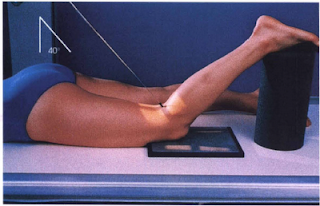
Image Receptor Size: 8 x 10
SID: 40"
Patient
position
1) Patient is prone
2) Flex the knee 40-50 degrees
and support the foot
3) Center the proximal half of the image
receptor to the knee joint
4) No rotation of the knee
5)
Shield gonads
Central Ray
• Perpendicular to the long axis
of the leg (40-50 degrees caudad), centered to the knee
joint
Structures Shown
• Open intercondylar fossa
•
Intercondyloid emminences
• Knee joint with soft tissue
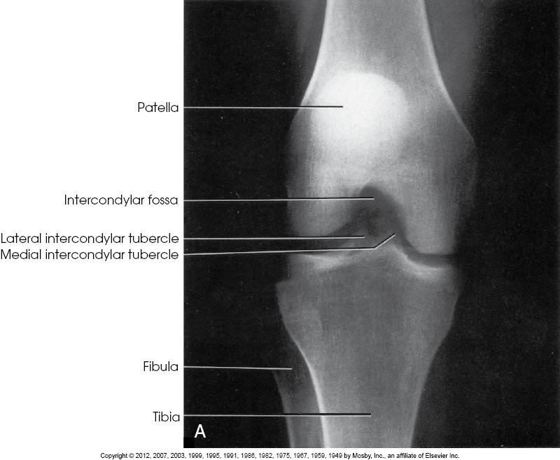
PA Axial of the intercondyloid fossa, Camp-Coventry Method, Tunnel View

Image Receptor Size: 8 x 10
SID: 40"
Patient
position
1) Patient is supine - sitting if possible
2) Flex
the knee so the femur forms a 60 degree angle to the tibia
3)
Place the image receptor under the knee
4) Shield
gonads
Central Ray
• Perpendicular to the long axis of the
tibia entering the knee 1/2" below the apex of the
patella
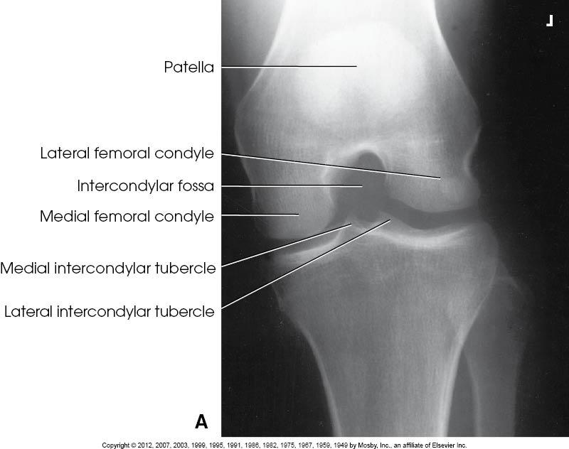
Structures Shown
• Open intercondylar fossa
•
Intercondyloid emminences
• Knee joint
• Soft tissue

AP Axial of the intercondyloid fossa, Beclere Method, Tunnel view
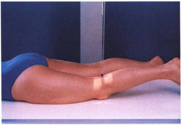
Image Receptor Size: 8 x 10
SID: 40"
Patient
position
1) Place the patient in the prone position.
2) If
the knee is painful, place one sandbag under the thigh and another
under the leg to relieve pressure on the patella.
3) Center the
IR to the patella.
4) Adjust the position of the leg to place the
patella parallel with the plane of the IR. This usually requires that
the heel be rotated 5 to 10 degrees laterally
Central Ray
•
Perpendicular to the midpopliteal area exiting the patella
•
Collimate closely to the patellar area.
Structures Shown
•
Patella completely superimposed by the femur
• Soft tissue and
bony trabecular detail

PA patella
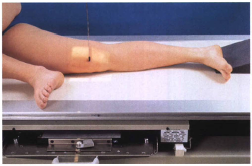
Image Receptor Size: 8 x 10
SID: 40"
Patient
position
1) Place the patient in the lateral recumbent
position.
2) Ask the patient to turn onto the affected hip. A
sandbag may be placed under the ankle for support.
3) Have the
patient flex the unaffected knee and hip, and place the unaffected
foot in front of the affected limb for stability.
4) Flex the
affected knee approximately 5 to 10 degrees. Increasing the flexion
reduces the patellofemoral joint space.
5) Adjust the knee in the
lateral position so that the femoral epicondyles are superimposed and
the patella is perpendicular to the IR
6) Shield gonads.
7)
Center the IR to the patella.
Central Ray
• Perpendicular to
the IR, entering the knee at the midpatellofemoral joint
•
Collimate closely to the patellar area.
Structures Shown
•
Knee flexed 5 to 10 degrees
• Open patellofemoral joint
space
• Soft tissue and bony trabecular detail

Lateral patella

Image Receptor Size: 8 x 10
SID: 40"
Patient
position
1) Patient is prone
2) Flex the knee as much as
possible or until patella is perpendicular to the image
receptor
3) Place the image receptor under the knee centered to
the femoropatellar joint space
4) Collimate
5) Shield
gonads
Central Ray
• Perpendicular to the femoropatellar
joint space. (The degree of angulation will depend upon the degree of
flexion of the knee)
Structures Shown
• *Vertical fractures
of the patella*
• Open patellofemoral articulation
• Patella
in profile
NOTE:
This projection may be performed with the
patient supine (seated
Knee is flexed and the image receptor is
placed on the anterior surface of the femur
Central ray is angled
upward, perpendicular to the femoropatellar joint space
Tangential patella, Sattegast Method, Sunrise View

Image Receptor Size: 8 x 10
SID: 40"
Patient
position
1) Patient is prone
2) No rotation of the
knee
3) Flex the affected knee so the tibia/fibula forms a
50°-60° angle with the table
4) Support the leg
5) Shield
patient
6) Collimate
Central Ray
• 45° cephalad through
the patellofemoral joint
Structures Shown
•
Subluxation
• Patellar fractures
• Patella in profile
•
Open patellofemoral joint
NOTE:
Usually recommended both
knees be examined for comparison
Tangential patella, Hughston Method

Image receptor Size: 10 x 12
SID: 6 foot
Patient
position
1) Using the Axial Viewer device, elevate the patient's
knees approximately 2 inches to place the femora parallel with the
tabletop
2) Adjust the angle of knee flexion to 40 degrees.
(Merchant reported that the degree of angulation may be varied between
30 degrees and 90 degrees to show various patellofemoral
disorders.)
3) Strap both legs together at the calf level to
control leg rotation and allow patient relaxation.
4) Place the
IR perpendicular to the central ray and resting on the patient's shins
(a thin foam pad aids comfort) approximately 1 foot distal to the
patellae.
5) Ensure that the patient is able to relax. Relaxation
of the quadriceps femoris is crucial for an accurate diagnosis. If
these muscles are not relaxed, a subluxated patella may be pulled back
into the intercondylar sulcus, showing a false normal
appearance.
6) Record the angle of knee flexion for
reproducibility during follow-up examinations because the severity of
patella subluxation commonly changes inversely with the angle of knee
flexion.
7) Shield gonads.
Central Ray
• Perpendicular
to the IR
• With 40-degree knee flexion, angle the central ray 30
degrees caudad from the horizontal plane (60 degrees from vertical) to
achieve a 30-degree central ray-to-femur angle. The central ray enters
midway between the patellae at the level of the patellofemoral joint
(superior aspect of patella).
Structures Shown
• Patellae in
profile
• Femoral condyles and intercondylar sulcus
• Open
patellofemoral articulation
• Soft tissue and bony trabecular detail
Tangential patella, Merchant Method
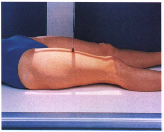
Image Receptor Size: 14 x 17
SID: 40" (bucky)
Patient
position
1) Patient is supine
2) Center the affected thigh
to the image receptor, making sure the joint closest to the area of
interest is on the image receptor.
3) To include hip, place the
top of the image receptor at the level of the ASIS and rotate the leg
10-15° internally (to place the neck in profile). To include knee,
place the bottom of the image receptor 2" below the knee joint
and make sure epicondyles are parallel to the image receptor
4)
Shield gonads
5) Obtain a second radiograph to include the other
joint
Central Ray
• Perpendicular to mid femur and centered
to the image receptor
Structures Shown
• Majority of the
femur and joint closest to the area of interest
• Femoral neck
not foreshortening on proximal femur
• No rotation
• Any
orthopedic appliance in its entirety
AP of the femur (distal)
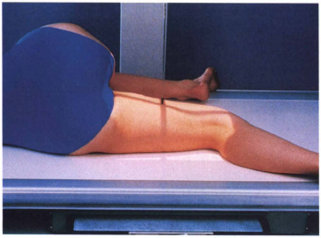
Image Receptor Size: 14 x 17
SID: 40" (bucky)
Patient
position
1) Patient turns onto affected side.
2) If the knee
joint is to be included, place the uppermost extremity forward
3)
Flex the knee about 45°
4) Femoral epicondyles are perpendicular
to the image receptor
5) Include the knee joint (image receptor
is about 2" below knee joint)
6) If the hip joint is to be
included, place the top of the image receptor at the level of the
ASIS.
7) Place the uppermost extremity posteriorly.
8)
Rotate the pelvis back from the lateral position approximately 10-15
degrees.
9) Shield gonads
10) Obtain a second radiograph to
include the other point
Central Ray
• Perpendicular to mid
femur and center of the image receptor
Structures Shown
•
Lateral projection of 3/4 of femur and the joint closest to the point
of interest
• Any orthopedic appliance in its entirely
Lateral of the femur, Mediolateral (distal)
Image Receptor Size: 14 x 17
SID: 40"
Patient
position
1) Patient is supine
2) Unless unable, internally
rotate the feet 15-20 degrees to place the femoral necks parallel with
the image receptor
3) No rotation of the pelvis
4) Top of
the image receptor should be 1-1½ " above the crests
5)
Suspend respiration
Central Ray
• Perpendicular centered to
the image receptor (approxiately 2" superior to the symphysis
pubis or 2" inferior to the ASIS")
Structures
Shown
• Entire pelvis
• Head, neck and trochanters in profile
AP of the Pelvis
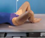
Image Receptor Size: 14 x 17
SID: 40"
Patient
position
NOTE: THIS PROJECTION IS NOT PERFORMED ON PATIENTS
SUSPECTED OF HAVING A FRACTURE!
BILATERAL
1) Patient is
supine
2) Top of the image receptor is placed 1-1½ above the
crests (1" superior to the symphysis pubis)
3) Flex knees,
feel up as much as possible
4) Abduct the thighs (between 25-45
degrees) and place soles of feet together
5) Suspend
respiration
UNILATERAL
1) Patient is supine
2) ASIS of
affected side is centered to the image receptor
3) Flex the knee
of the affected side, draw foot up
4) Abduct thigh approximately
45 degrees and place sole of foot on opposite leg
5) Suspend
respiration
Central Ray
Bilateral
• Perpendicular,
centered to the image receptor, approximately 1" superior to
symphysis pubis
Unilateral
• Perpendicular to the femoral
neck
Structures Shown
• Acetabulum, femoral head and
neck
• Lesser trochanter
• No rotation of pelvis for Bilateral
AP Oblique of the Pelvis, Modified Cleaves Method, Frogleg (Bilateral)
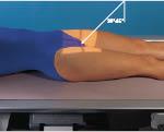
Image receptor Size: 10 x 12
SID: 40"
Patient
position
1) Patient is supine
2) No rotation of the
pelvis
3) Suspend respiration
Central
Ray
Males
20°-35° cephalad centered 2" distal to the
pubis symphysis
Females
30°-45° cephalad centered 2"
distal to the pubis symphysis
Structures Shown
• Pubis &
Ischial rami without foreshortening
• Symmetrical obturator
foramen
• Hip joints
AP Axial of the Pelvis, Outlet, Taylor Method

Image Receptor Size: 8 x 10
SID: 40"
1) Patient is
supine
2) No rotation
3) Center the Image receptor to the
level of the greater trochanters
4) Suspend
respiration
Central Ray
• 40° caudad entering at the
ASIS
Structures Shown
• Symmetrical pubic bones and ischial
spines
• Hip joints
• Anterior pelvic bones
AP Axial of the pelvis, Inlet, Bridgeman Method
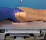
Image Receptor Size: 10 x 12 Lengthwise
SID:
40"
Patient position
1) Patient is supine
2)
Center the image receptor to the level of the greater trochanter (Top
of the image receptor at the ASIS) and 2" medial to the
ASIS
3) Unless contraindicated, internally rotate affected foot
15-20 degrees
4) Suspend respiration
Central Ray
•
Perpendicular to the femoral neck
LOCALIZATION OF HIP
JOINT:
Femoral head - 1½" distal to the midpoint of a line
between ASIS and the superior margin of the symphysis
pubis
Femoral neck - 2½" distal to the midpoint of a line
drawn between ASIS and the superior margin of the symphysis
pubis
Structures Shown
• Femoral head &
acetabulum
• Greater trochanter in profile
• Entire femoral
neck not foreshortened
• Any orthopedic appliance in its entirety
AP of the Hip
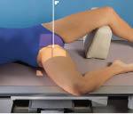
Image Receptor Size: 10 x 12 Lengthwise or crosswise
SID:
40"
Patient position
1) Turn patient slightly toward
affected side
2) Center affected hip to middle of image
receptor
3) Flex knee, draw leg up and abduct the thigh
4)
Suspend respiration
Central Ray
• Perpendicular through the
hip joint - Lauenstein Method 20-25° cephalic - Hickey
Method
Structures Shown
• Relationship of femoral head to
acetabulum
• Hip joint
• Lateral hip
Lateral of the hip, Mediolateral, Lauenstein & Hickey Methods, Frogleg
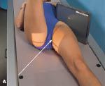
Image Receptor Size: 10 x 12 with grid Lengthwise
SID:
40"
Patient position
1) Patient is supine
2) If
patient is extremely thin, elevate the affected hip slightly
3)
Place the image receptor against the hip with upper border of the
image receptor at the crest
4) If possible, internally rotate the
affected leg 15°-20°
5) Flex the unaffected knee and lift
unaffected leg in a vertical position (As high up as possible)
6)
Have patient hold leg in position or place on a support
7)
Suspend respiration
Central Ray
• Perpendicular to the long
axis of the femoral neck, centered to the hip joint
Structures
Shown
• Femoral head, neck & trochanters
•
Acetabulum
• Ischial tuberosity below the femoral head
• Any
orthopedic appliance
Axiolateral of the hip, Danelius-Miller, Cross-table
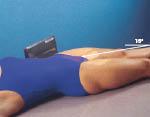
Image Receptor Size: 10 x 12 (24 X 30)
SID:
40"
Patient position
1) Patient supine with the
affected side near the edge of the table
2) Place the grid &
image receptor at the crest of the affected hip
3) Adjust the
grid parallel to the axis of the femoral neck & tilt it back
15°
4) Suspend respiration
Central Ray
• 15°
posteriorly. Perpendicular to the femoral neck and image
receptor
Structures Shown
• Hip joint with acetabulum
•
Femoral head, neck & trochanters
• Any orthopedic appliance
in its entirety
Modified Axiolateral of hip, Clements-Nakayama Modification
Image Receptor Size: 10 x 12
SID: 40"
Patient
position
INTERNAL OBLIQUE
1) Patient is supine
2) Top
of the image receptor at the ASIS
3) Rotate the affected side up
45°
4) Suspend respiration
Central Ray
• Perpendicular
to the image receptor, entering at the the pubic
symphysis
EXTERNAL OBLIQUE
1) Patient supine
2) Top of
image receptor at the ASIS
3) Rotate the affected side up
45°
4) Suspend respiration
Structures Shown
•
Acetabulum
• Femoral head
AP Oblique of hip, Judet Method
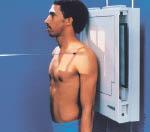
Image receptor Size: 10 x 12 Crosswise
SID:
40"
Patient position
1) Patient is upright or recumbent
supine
2) Center the clavicle to the image
3) Shield
patient
4) Suspend respiration
Central Ray
•
Perpendicular to midshaft of clavicle
Structures Shown
•
Entire clavicle
AP of the clavicle
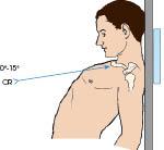
Image Receptor Size: 10 x 12 Crosswise
SID: 40" (Upright or
supine)
Patient position
1) Patient is upright,
supine
2) Have the patient lean backwards in a lordotic
position
3) Center the clavicle to the image receptor
4)
Shield patient
5) Suspend respiration after full
inspiration
Central Ray
• Lordotic position = 0 - 15°
cephalic, centered to midshaft of the clavicle.
NOTE: If the
patient cannot assume a lordotic position, they can remain supine with
a 15 - 30° cephalic angulation of the tube
Structures
Shown
• Axial image of the entire clavicle projected above the
ribs
• Clavicle in a horizontal placement
NOTE: For a PA
axial, the image receptor size, SID, patient positioning and
structures shown are all the same as the AP Axial except the patient
is prone and the Central Ray is angled 15-30° caudad
AP axial of the clavicle
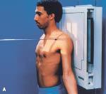
Image Receptor Size: 10 x 12
SID: 40" (Upright or
Supine)
Patient position
1) Patient is supine. (either
recumbent or upright)
2) Center the image receptor 1"
inferior to the coracoid process
3) The patient may have to be
rotated slightly toward the affected shoulder
4) Supinate the
hand and abduct the arm slightly
5) Humeral epicondyles are
parallel to the image receptor
6) Shield patient
7) Suspend
respiration
Central Ray
• Perpendicular to the patient,
entering 1" inferior to be coracoid process
Structures
Shown
• Humeral head and greater tubercle in profile
•
Shoulder joint
AP of the shoulder, External rotation
Image Receptor Size: 10 x 12 Crosswise or Lengthwise
SID:
40"
Patient position
1) Patient is supine. (either
recumbent or upright)
2) Center the image receptor 1"
inferior to the coracoid process
3) The patient may have to be
rotated slightly toward the affected shoulder
4) Rest the palm of
the hand against the thigh
5) Humeral epicondyles are at 45°
oblique angle
Central Ray
• Perpendicular to the patient,
entering 1" inferior to be coracoid process
Strictures
Shown
• Greater tubercle partially superimposed on the humeral head
AP of the shoulder, Neutral rotation
Image Receptor Size: 10 x 12
SID: 40"
Patient
position
1) Patient is supine. (either recumbent or
upright)
2) Center the image receptor 1" inferior to the
coracoid process
3) The patient may have to be rotated slightly
toward the affected shoulder
4) Flex the elbow slightly,
internally rotate the arm so that the back of the hand rests on the
hip
5) Humeral epicondyles are perpendicular to the image
receptor
Central Ray
• Perpendicular to the patient,
entering 1" inferior to be coracoid process
Structures
Shown
• Lesser tubercle in profile
• Shoulder joint with
humeral head overlapping glenoid cavity
• True lateral of
proximal humerus
AP of the shoulder, Internal rotation
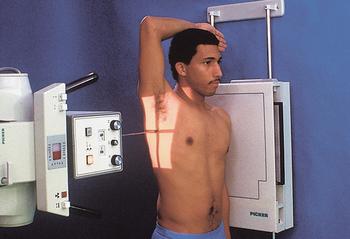
Image Receptor Size: 10 x 12 Lengthwise
SID: 40" Upright or
Supine
Patient position
1) Patient is upright with the
affected side against the image receptor
2) Raise the uninjured
arm over the head, or as much as possible
3) Surgical neck of
affected arm is centered to the image receptor
4) Shield
patient
5) Respiration is one of two choices
a) Hold on full
inspiration
b) Use a breathing technique, with a 4-5 second
exposure time (3 seconds remaining)
Central Ray
•
Perpendicular to the surgical neck at the midcoronal plane
*NOTE:
If the patient cannot raise the unaffected arm, a 10-15° cephalic tube
angle can be utilized
Structures Shown
• Lateral shoulder
through the thorax
• Proximal humerus
Transthoracic Lateral of the shoulder, Lawrence Method
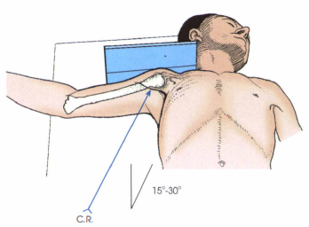
Image Receptor Size: 8 x 10
SID: 40"
Patient
position
1) Patient is supine (recumbent)
2) If the patient
is extremely thin, may need to elevate the affected shoulder (above
3")
3) Abduct the arm as much as possible (try to achieve a
90° angle with the body)
4) Keep the humerus in external
rotation
5) Turn the head away from the affected side and place
the image receptor against the top of the shoulder, close to the
neck
6) Shield patient
7) Suspend respiration
Central
Ray
• Horizontally and perpendicular to the image receptor,
through the axilla
Structures Shown
• Proximal humerus &
shoulder joint
• Coracoid process
• Soft tissue
Inferosuperior Axial of the shoulder, Lawrence Method, Axillary
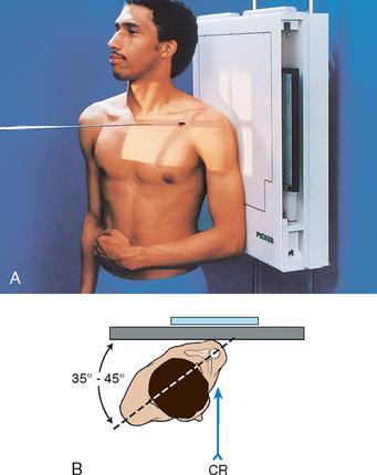
Image Receptor Size: 10 x 12
SID: 40" Crosswise or
Lengthwise
Patient position
1) Patient is supine or
upright
2) Center the image receptor to the shoulder joint.
(2" medial & 2" inferior to the supralateral
border)
3) Rotate the patient 35-45° toward the affected
side
4) Abduct the arm slightly and place it on the abdomen in
internal rotation
5) Shield patient
6) Suspend
respiration
Central Ray
• Perpendicular to the glenoid
cavity, 2" medial and 2" inferior to the superior/lateral
border of the shoulder
Structures Shown
• Open shoulder
joint
• Glenoid cavity in profile
AP Oblique of the shoulder, Grashey Method
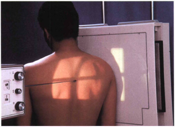
Image Receptor Size: 10 x 12
SID: 40"
Patient
position
1) Patient is upright
2) Rotate the patient so the
midcoronal plane forms an angle of 45-60°
3) Center the image
receptor to the shoulder joint
4) Shield patient
5) Suspend
respiration
Central Ray
• Perpendicular to the shoulder
joint
Structures Shown
• Acromion projected laterally &
free of superimposition
• Coracoid process
• Scapula in
profile
**Useful in the elevation of shoulder
dislocations
*NOTE: When the patient is severly injured, RPO/LPO
projections may be obtained
PA Oblique of the shoulder, Scapular Y
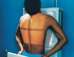
Image Receptor Size: 14 x 17 Crosswise
SID: 40" Upright or
recumbent
Patient position
1) Patient is prone, either
recumbent or upright
2) Adjust the top of the image receptor
1½" above the shoulders
3) Rest hands on the hips, palms
turned outward
4) Rest the head on the chin
5) Shield
patient
6) Suspend respiration after full
inspiration
Central Ray
• Perpendicular, centered to the
image receptor at the level of T7 and median sagittal
plane
Structures Shown
• *PA best demonstrates ribs above
the diaphragm*
• Rib pairs 1-9
PA of the ribs, Upper Anterior Ribs
Image Receptor Size: 14 x 17
SID: 40"
Patient
position
1) Patient is prone, either recumbent or upright
2)
Adjust the bottom of the image receptor to the level of the iliac
crests
3) Shield patient
4) Suspend respiration after full
inspiration
Central Ray
• Perpendicular, center to the image
receptor and median sagittal plane
Structures Shown
• Lower
rib pairs, 8-12
PA of the Ribs, Lower Anterior Ribs
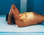
Image Receptor Size: 14 x 17
SID: 40" Upright or
recumbent
Patient position
1) Patient is supine
2)
Place the top of the image receptor 1½ above relaxed shoulders
3)
Rest patient's hands against hips, palms outward
4) Shield
patient
5) Suspend respiration after full
inspiration
Central Ray
• Perpendicular, centered to the
image receptor and the median sagittal plane
Structures
Shown
• Rib pairs, 1-10
AP of the ribs, Upper Posterior Ribs
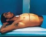
Image Receptor Size: 14 x 17 Crosswise
SID:
40"
Patient position
1) Patient is supine
2) Place
the bottom of the image receptor at the level of the iliac
crests.
3) Place arms in a comfortable position
4) Shield
patient
5) Suspend respiration at the end of the full
exhalation
Central Ray
• Perpendicular, centered to the
image receptor and median sagittal plane
Structures Shown
•
Rib pairs, 8-12
AP of the Ribs, Lower Posterior Ribs

Image Receptor Size: 14 x 17 Lengthwise
SID: 40" Upright or
recumbent
Patient position
1) Patient is supine, either
recumbent or upright
2) Rotate the body 45° into an RPO
position
3) Abduct the arm of the affected side and elevate it;
Abduct the opposite arm and place it on the hip
4) Center the
image receptor to T7, with the top of the image receptor 1½"
above relaxed shoulders for upper ribs.
5) Center the bottom of
the image receptor at the level of the iliac crests, for lower
ribs
6) Shield patients
7) Respiration is suspended after
full inhalation for upper ribs. Full exhalation for lower
ribs
Central Ray
• Perpendicular, centered to the image
receptor and midway between the median sagittal plane and lateral
border of the affected side
Structures Shown
• Axillary
portion of the ribs are projected free of superimposition
• Ribs
are either elongated or foreshortened, depending upon the oblique
AP Oblique of the Ribs, RPO

Image Receptor Size: 14 x 17 Lengthwise
SID: 40" Upright or
recumbent
Patient position
1) Patient is supine, either
recumbent or upright
2) Rotate the body 45° into an LPO
position
3) Abduct the arm of the affected side and elevate it;
Abduct the opposite arm and place it on the hip
4) Center the
image receptor to T7, with the top of the image receptor 1½"
above relaxed shoulders for upper ribs.
5) Center the bottom of
the image receptor at the level of the iliac crests, for lower
ribs
6) Shield patients
7) Respiration is suspended after
full inhalation for upper ribs. Full exhalation for lower
ribs
Central Ray
• Perpendicular, centered to the image
receptor and midway between the median sagittal plane and lateral
border of the affected side
Structures Shown
• Axillary
portion of the ribs are projected free of superimposition
• Ribs
are either elongated or foreshortened, depending upon the oblique
AP Oblique of the Ribs, LPO
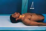
Image Receptor Size: 8 x 10 Lengthwise
SID: 40" or
72"
Patient position
1) Patient is supine, either
recumbent or upright
2) Extend the patient's chin slightly (this
prevents superimposition of the mandible and midcervical
vertebrae)
3) Center the image receptor to the level of C4 and
median sagittal place
4) Shield patient
5) Suspend
respiration
Central Ray
• 15 - 20° cephalic, entering at C4
(Adam's Apple)
Structures Shown
• Lower 5 cervical
vertebrae
• Area from C3 - T2
• Open intervertebral disk spaces
AP Axial of the Cervical spine
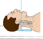
Image Receptor Size: 8 x 10 Lengthwise
SID: 40" or
72"
Patient position
1) Patient is supine, either
recumbent or upright
2) Center the image receptor to the level of
C2
3) Have the patient open their mouth as wide as possible and
adjust the head so a line a drawn from the lower edge of the upper
incisors to the tip of the mastoid process is perpendicular to the
image receptor
4) Shield patient
5) Suspend respiration and
phonate "ah" (This places the tongue on the floor of the
mouth)
Central Ray
• Perpendicular to the midpoint of he
open mouth (corners of the lips)
Structures Shown
• Dens,
atlas and axis projected through the open mouth C1 - C2 articulation
AP of the Cervical Vertebrae, Open Mouth, For Atlas & Axis
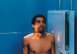
Image Receptor Size: 8 x 10 Lengthwise
SID:
72"
Patient position
1) Place patient in a true lateral
position, upright
2) Rest the shoulder against the vertebral grid
device and depress the shoulders as much as possible (hold sandbags if
necessary)
3) The top of the image receptor should be about
1" above the EAM (external auditory meatus)
4) Elevate the
chin slightly and protrude the mandible if possible (bite upper
lip)
5) Ask the patient to look steadily at one point on the
wall
5) Shield patient
6) Suspend respiration on full
exhalation
Central Ray
• Horizontal and perpendicular to
C4
Structures Shown
• All seven cervical vertebrae with
spinous processes in profile
• Mandible is not superimposed over
C1, C2
• Soft tissue
Lateral R or L, Grandy Method

Image Receptor Size: 8 x 10 Lengthwise
SID:
72"
Patient position
1) Same positioning and central
ray direction as a lateral
• HYPERFLEXION: Draw the chin as close
to the chest as possible
• HYPEREXTENSION: Elevate the chin as
much as possible and extend the head back
Structures Shown
•
HYPERFLEXION - Spinous processes separated and elevated
•
HYPEREXTENSION - Spinous processes depressed (close together)
•
Demonstrates normal movement or an absence of movement if trauma or diseased
Lateral R or L, Hyperflexion/Hyperextension
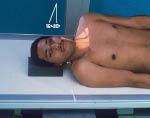
Image Receptor Size: 8 x 10
SID: 72" (preferred) or
40"
Patient position
1) Patient is supine, either
recumbent or upright
2) Rotate the body 45° in either an RPO
position
3) Center the image receptor to C3 (place the top of the
image receptor at the level of the top of the ear)
4) Have the
patient look straight ahead, elevate the chin and protrude the
mandible
5) Shield patient
6) Suspend
respiration
Central Ray
• 15 - 20° cephalic entering
C4
Structures Shown
• Open intervertebral foramina farthest
from the film
• Open intervertebral disk spaces
• All seven
cervical vertebrae
AP Axial Oblique of Cervical vertebrae, RPO
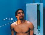
Image Receptor Size: 8 x 10
SID: 72" (preferred) or
40"
Patient position
1) Patient is supine, either
recumbent or upright
2) Rotate the body 45° in either an LPO
position
3) Center the image receptor to C3 (place the top of the
image receptor at the level of the top of the ear)
4) Have the
patient look straight ahead, elevate the chin and protrude the
mandible
5) Shield patient
6) Suspend
respiration
Central Ray
• 15 - 20° cephalic entering
C4
Structures Shown
• Open intervertebral foramina farthest
from the film
• Open intervertebral disk spaces
• All seven
cervical vertebrae
AP Axial Oblique of Cervical vertebrae, LPO
Always perform a cross-table lateral cervical spine for severe injury
FIRST. Do not move the patient or remove cervical
collars.
Depress the shoulders as much as possible (Sometimes a
physician will pull on the arms to depress the shoulders)
Trauma (of the cervical vertebrae)
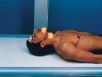
Image Receptor Size: 8 x 10
SID: 40"
Patient
position
1) Patient is supine
2) Center the image receptor
to the level of the tips of the mastoid processes
3) Extend the
chin so the chin & the mastoid process are perpendicular
4)
Shield patient
5) Collimate
Central Ray
• Perpendicular
entering distal to the tip of the chin
Structures Shown
•
Dens within the foramen magnum
• No rotation
AP of the cervical vertebrae, Fuchs Method

Image Receptor Size: 10 x 12
SID: 40"
Patient
position
1) Place the patient in a true lateral position, upright
or recumbent
2) Elevate the arm closest to the image receptor and
rest the forearm on the patient's head
3) Depress the opposite
shoulder and rotate the arm slightly anterior
4) Center the image
receptor at the level of C7 - T1
5) Shield patient
6)
Suspend respiration or use breathing technique
Central Ray
•
Perpendicular to C7 - T1 if shoulder is depressed
• 3 - 5° caudad
if shoulder is not depressed
Structures Shown
• Lateral
cervicothoracic vertebrae projected between the two shoulders
Lateral of the cervicothoracic region (R or L), Swimmers
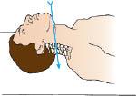
Image Receptor Size: 8 x 10 or 10 x 12 Lengthwise
SID:
40"
Patient position
1) Patient is supine
2)
Depress the shoulders
3) Hyperextend the patient's head
4)
Shield patient
5) Suspend respiration
Central Ray
•
20-30° caudad, directed to C7
Structures Shown
• Vertebral
arch structures
• Articular processes
*NOTE: This procedure
must not be attempted until cervical spine pathology or fracture has
been ruled out
AP Axial of the cervicothoracic region, Vertebral Arch, Pillars
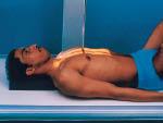
Image Receptor Size: 14 x 17 or 7 x 17 Lengthwise
SID:
40"
Patient position
1) Patient is supine
2) Flex
the knees and place the soles
3) Center the image receptor to T7
(approximately 3-4" distal to jugular notch) or 1½ - 2"
above relaxed shoulders for the top of the image receptor
4)
Center to the median sagittal plane
5) Shield patient
6)
Suspend respiration after full exhalation
Central Ray
•
Perpendicular approximately half way between the jugular notch and
xiphoid process
Structures Shown
• AP of all twelve thoracic vertebrae
AP of thoracic spine
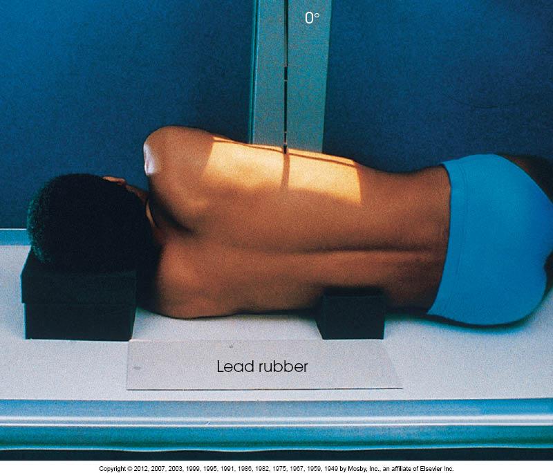
Image Receptor Size: 14 x 17 or 7 x 17
SID:
40"
Patient position
1) Patient is placed in a true
lateral position
2) Elevate the head to the long axis of the
vertebral column
3) Flex the knees and hips into a comfortable
position
4) Center the image receptor to T7 or place the top of
the image receptor 1½ - 2" above relaxed shoulders
5) Adjust
the arms at right angles of the body
6) Shield patient
7)
Suspend respiration after full exhalation or use breathing technique
(low mA, high second)
Central Ray
• Perpendicular to T7 and
posterior half of thorax
Structures Shown
• Twelve thoracic
vertebrae
• Intervertebral foramina
• Open intervertebral
disk spaces
**NOTE: To improve image quality, a lead placed on
the table behind the patient's back to attenuate the scatter radiation
Lateral of thoracic vertebrae (R or L)
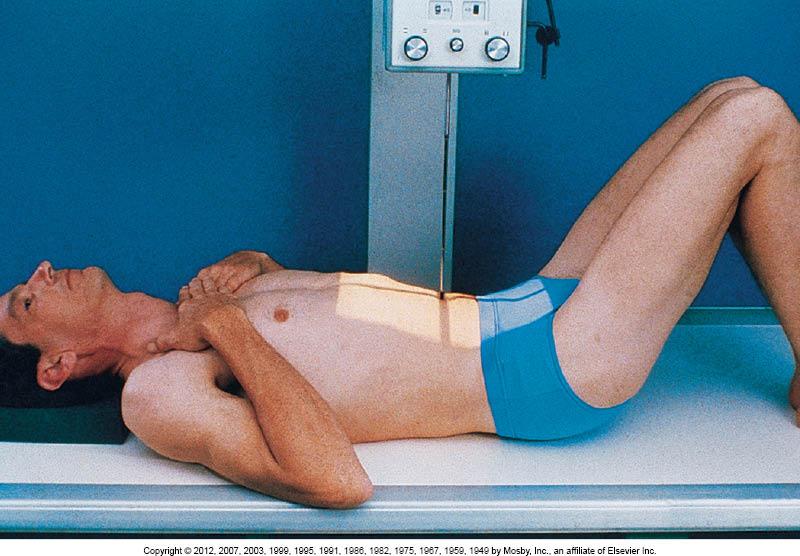
Image Receptor Size: 14 x 17 or 11 x 14 Lengthwise
SID: 40"
(48" is suggested)
Patient position
1) Patient is
supine
2) Flex the knees hips and place the soles of the feet on
the table (This reduces the lordotic curvature of the lumbar
region)
3) Center the image receptor at the level of the iliac
crests for a 14 x 17 or 1½" above the crests for
C an 11 x
14
4) Center the image receptor to the median sagittal plane
5) Shield patient is possible
6) Suspend respiration at the
end of expiration
Central Ray
• Perpendicular to the level
of the iliac crests (L4) for a 14 x 17 or 1½" above the crests
(L3) for an 11 x 14
Structures Shown
• All five lumbar
vertebrae
• Open intervertebral disk spaces
*NOTE: PA
projection significantly reduces the gonadal dose as compared to an AP
projection
• Many radiologists request that limited collimation
be utilized, so the liver, kidney, spleen and psoas muscle margins are visualized**
AP of the lumbar spine
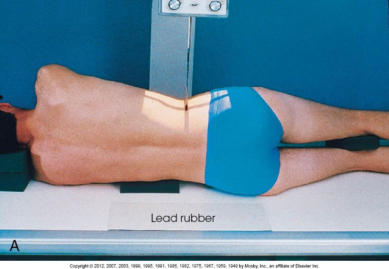
Image Receptor Size: 14 x 17 or 11 x 14
SID:
40"
Patient position
1) Place the patient in a true
lateral position (usually left)
2) Flex the knees and hips to a
comfortable position
3) Center the image receptor to the median
coronal plane and level of the iliac crests for a 14 x 17, 1½"
above the crest for an 11 x 14
4) If necessary, place a support
under the lower thorax and waist
5) Shield patient
6)
Suspend respiration after full exhalation
Central Ray
•
Perpendicular to the level of the iliac crests (L4) for a 14 x 17 and
median coronal plane
Structures Shown
• All five lumbar
vertebrae
• Open intervertebral foramina
**NOTE: To improve
image quality, a lead strip can be placed on the table behind the
patient's back to attenuate scatter radiation**
Lateral of the lumbar spine (R or L)
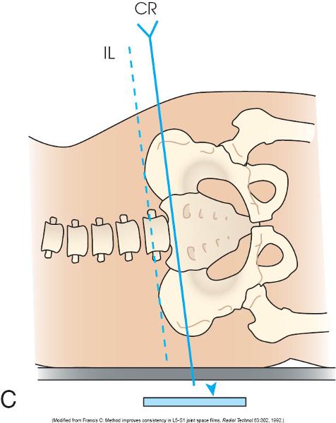
Image Receptor Size: 8 x 10 Lengthwise
SID:
40"
Patient position
1) Patient is placed in a true
lateral position
2) Extend the knees and hips to a comfortable
position
3) Center the image receptor to a point 2"
posterior to the ASIS and 1½" inferior to the iliac crest, along
the coronal plane
4) Shield patient if possible
5)
Collimate
6) Suspend respiration
Central Ray
•
Perpendicular if the patient's spine is horizontal - 2" posterior
to the ASIS and 1½" inferior to the iliac crest, along the
coronal plane
• 5° caudad for males, 8° caudad for females when
the spine is not horizontal
Structures Shown
• Open
lumbosacral joint
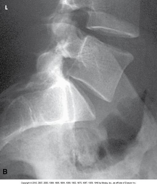
(L5 - S1) Lumbosacral Junction, Lateral of the lumbar spine (R or L)
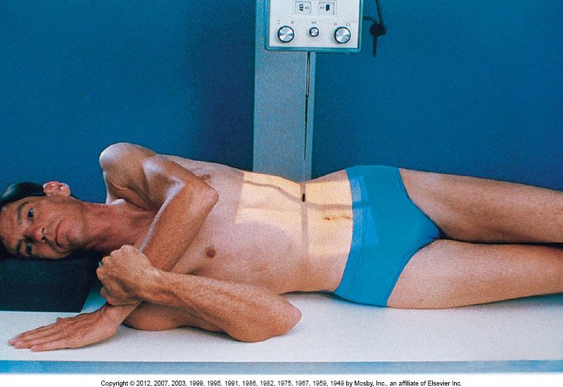
Image Receptor Size: 8 x 10 or 10 x 12
SID:
40"
Patient position
1) Patient is supine
2)
Rotate the patient 45° into an RPO or LPO position
3) Center the
spine to the image receptor (2" medial to the elevated ASIS)
approximately 1 - 1½" above the iliac crests at the level of
L3
4) Shield patient
5) Suspend respiration after
expiration
Central Ray
• Perpendicular, 1½" above the
crest at the level of L3 and 2" medial to the elevated
ASIS
Structures Shown
• Demonstrates the zygapophyseal
joints closest to the image receptor ("Scottie Dogs")
•
Both sides are done for comparison
**NOTE: In the PA Obliques
(RAO/LAO), the zygapophyseal joints farthest from the image receptor
are demonstrated**
AP Oblique of the lumbar spine, (RPO/LPO)
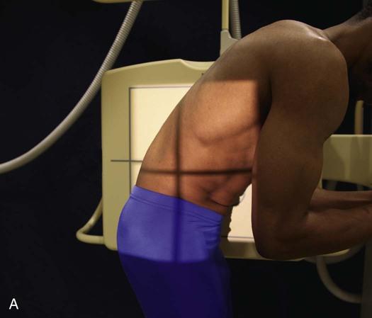
Image Receptor Size: 14 x 17 Lengthwise
SID:
40"
Patient position
1) Patient is standing
2)
Center the image receptor to the level of L3 (umbilicus)
3) Arms
are outside the area of interest
4) Have patient bend forward as
far as possible without rotation
5) Collimate
6) Suspend
respiration
Central Ray
• Perpendicular to
L3
Structures Shown
• Mobility of intervertebral
joints
• Include lower thoracic to sacrum
**NOTE: AP right
and left bending positions can be performed to demonstrate mobility of
the intervertebral joints. These studies are also used in patients
with early scoliosis to determine the presence of structural change
when bending to the right or left**
Lateral of the lumbar vertebrae, Weightbearing Method, Flexion
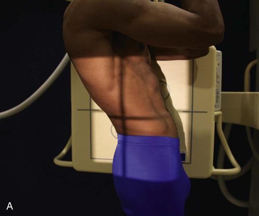
Image Receptor Size: 14 x 17 Lengthwise
SID:
40"
Patient position
1) Patient is standing
2)
Center the image receptor to the level of L3 (umbilicus)
3) Arms
are outside the area of interest
4) Have patient bend backwards
as far as possible without rotation
5) Collimate
6) Suspend
respiration
Central Ray
• Perpendicular to
L3
Structures Shown
• Mobility of intervertebral
joints
• Include lower thoracic to sacrum
**NOTE: AP right
and left bending positions can be performed to demonstrate mobility of
the intervertebral joints. These studies are also used in patients
with early scoliosis to determine the presence of structural change
when bending to the right or left**
Lateral of the lumbar vertebrae, Weightbearing Method, Extension
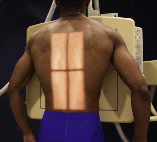
Image Receptor Size: 14 x 36
SID: 60" minimum
Patient
position
FIRST EXPOSURE
1) Patient is standing or seated
PA
2) Arms hang relaxed at the sides
3) Midsagittal plane is
centered to the image receptor is 1" below the iliac
crest
5) Shield gonads
6) Suspend respiration
SECOND
EXPOSURE
1) Elevate the patient's hip on the convex side
3-4" by having them step on a block
2) Midsagittal plane is
centered to the image receptor
3) Bottom on the image receptor is
1" below the iliac crest
4) Shield gonads
5) Suspend
respiration
Central Ray
• Perpendicular to the image
receptor
Structures Shown
• Thoracic and lumbar verterbae
Scoliosis series, PA of the lumbar spine, Ferguson Method
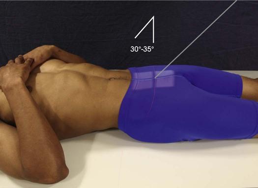
Image Receptor Size: 8 x 10 or 10 x 12
SID:
40"
Patient position
1) Patient is supine with their
legs extended
2) Center the image receptor 1½" superior to
the symphysis pubis
3) Suspend respiration
Central
Ray
• 30° cephalic for males, 35° cephalic for females, entering
the median sagittal plane, 1½" superior to the symphysis
pubis
Structures Shown
• Lumbosacral joint
•
Symmetrical image of sacroiliac joints free superimposition
AP Axial of the sacroiliac joints, Ferguson Method
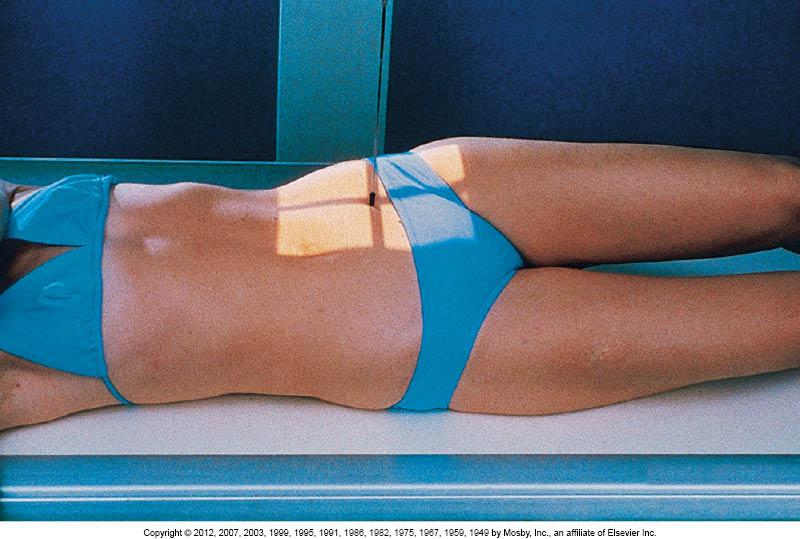
Image Receptor Size: 8 x 10 or 10 x 12
SID:
40"
Patient position
1) Patient is supine
2)
Elevate the side being examined 25-30°
3) Center the image
receptor to a point 1" medial to the elevated ASIS
4)
Collimate
5) Suspend respiration
Central Ray
•
Perpendicular entering 1" medial to the elevated
ASIS
Structures Shown
• Open SI joint farthest from the
film
• Both sides are examined for comparison
**NOTE: PA
Obliques (RAO/LAO) will demonstrate the SI joints closest to the film**
AP Oblique of sacroiliac joints(RPO/LPO)
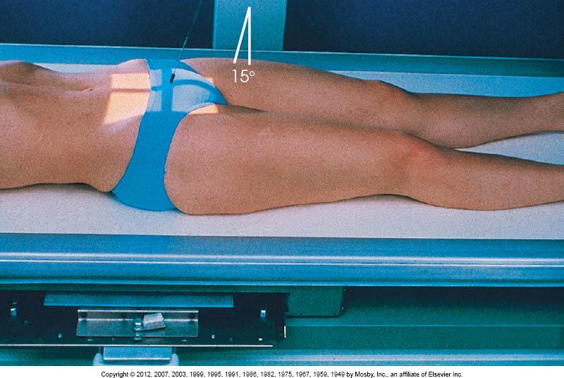
Image Receptor Size: 10 x 12 (Sacrum)
SID: 40"
Patient
position
1) Patient is supine with legs extended
2) Shield
gonads for men
3) Suspend respiration
Central Ray
• 15°
cephalic centered to a point 2" superior to the symphysis
pubis
Structures Shown
• Sacrum free of foreshortening and rotation
AP Axial of the Sacrum
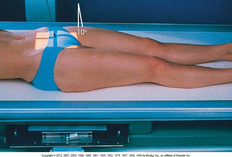
Image Receptor Size: 10 x 12 (Sacrum) 8x 10 (Coccyx)
SID:
40"
Patient position
1) Patient is supine with legs
extended
2) Shield gonads for men
3) Suspend
respiration
Central Ray
• 10° caudad, centered to a point
2" superior to the symphysis pubis
Structures Shown
•
Coccygeal segments not superimposed
AP Axial of the Coccyx
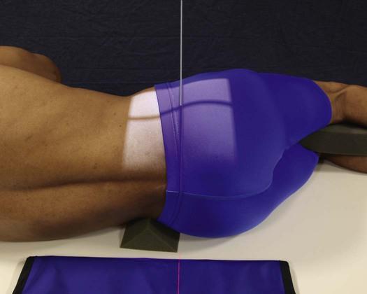
Image Receptor Size: 10 x 12 (Sacrum) 8x 10 (Coccyx)
Lengthwise
SID: 40"
Patient position
1) Place the
patient in a true lateral position
2) Flex the knees and hips
into a comfortable position
SACRUM
3) Place the top of the
image receptor to the level of the iliac crests and passing 3½"
posterior to the ASIS
4) Suspend respiration
Central
Ray
SACRUM
• Perpendicular to the level of the ASIS and a
plane 3½" posterior to the ASIS
COCCYX
• Perpendicular
through the coccyx at a point 3½" posterior to the ASIS and
2" inferior
Structures Shown
• Lateral sacrum & coccyx
Lateral of Sacrum and Coccyx (R or L)